





























Header
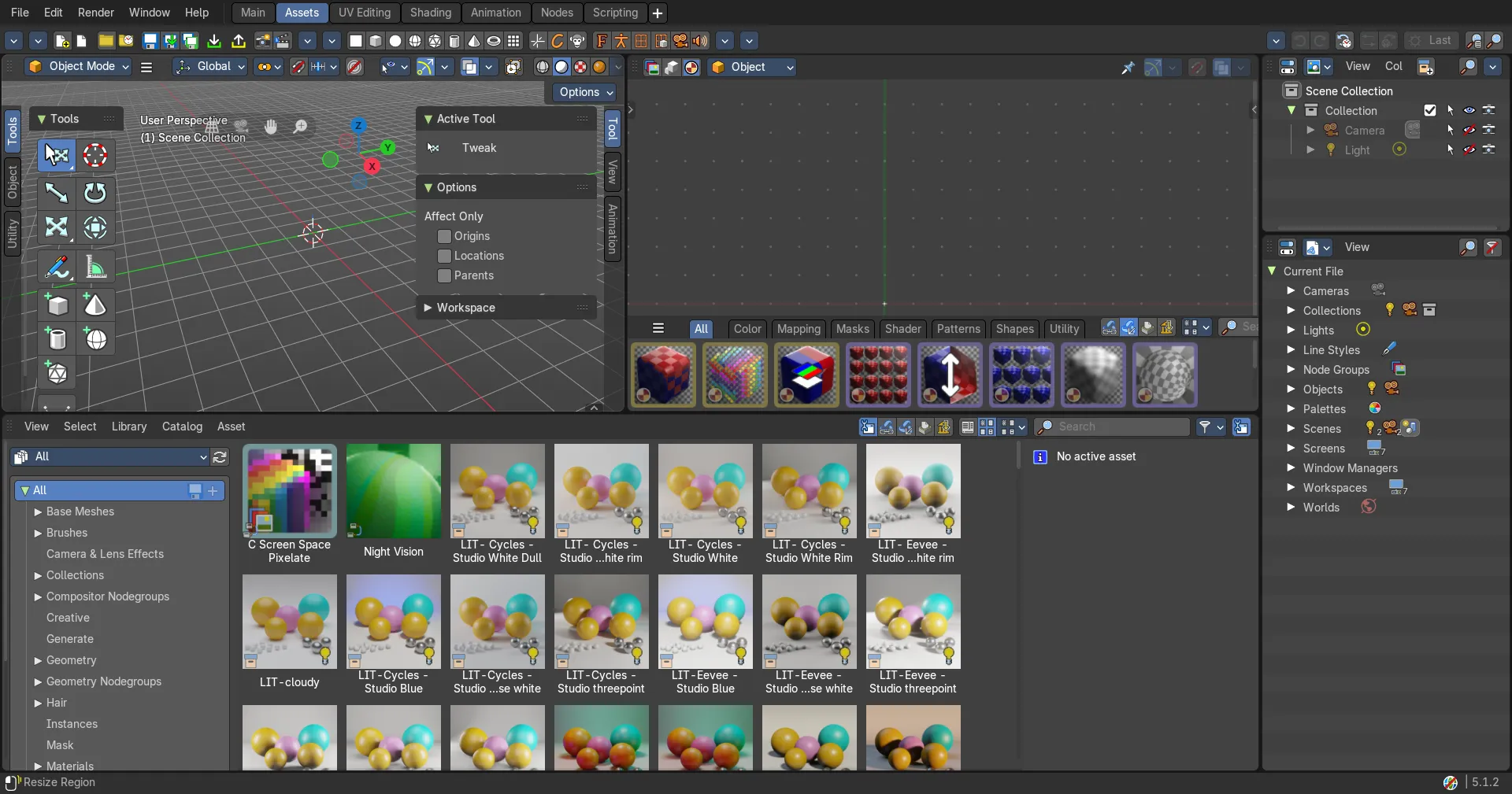
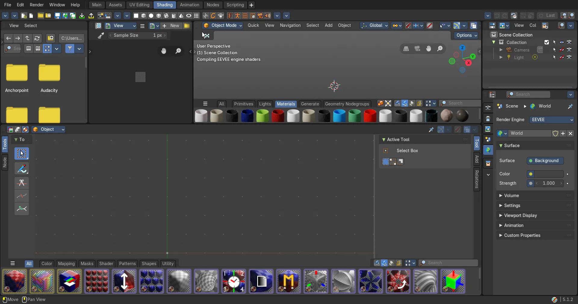
The Header contains various menus, navigation elements, settings and tools for the viewport.
UV Editor - Header
The Header contains various menus, navigation elements, settings and tools for the viewport. This content differs, dependent of the sub mode.
The header is divided into two areas. Left mode and menus. Right settings.

Switch to UV / Image editor
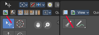
Sometimes you want to switch from the UV Editor to the Image Editor. Or vice versa. To continue at the unwrap or to paint a texture.
This two editors are connected by a menu that allows exactly that. A button in each header that switches to the other editor.
Header right click menus
The general right click menu functionality is explained in chapter 6 Editors introduction.
Editortype Menu
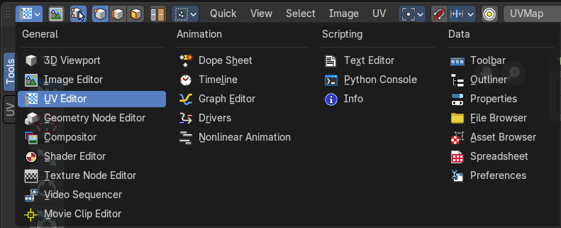
Bforartists is made of several editor types. Headers can display a menu where you can switch to other editor types.
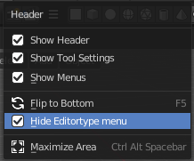
This menu is hidden by default. It is meant to edit the layouts, and should not be necessary for regular work. You can reveal it in the header right click menu.
Sub Modes
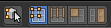
The UV Editor has two sub modes. Sync Off and Sync On.
UV Select Sync off
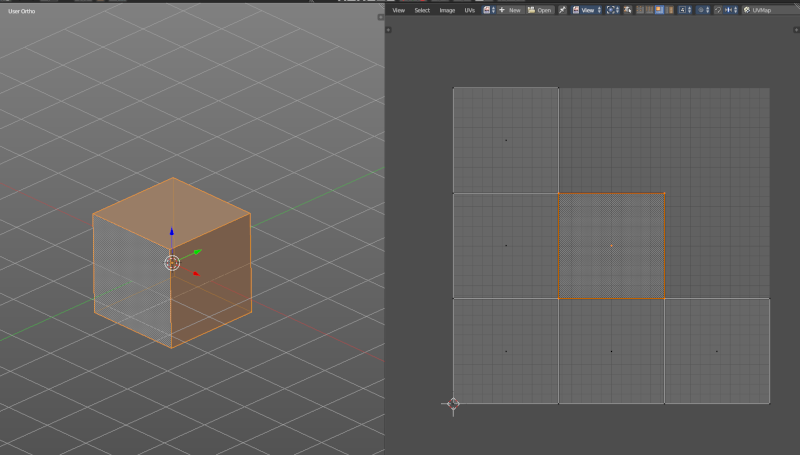
With UV Select Sync off you will be able to modify single UV elements, like whole UV patches. And the 3D view will not change its selection.
When you have some geometry in the 3D view not selected, then it will not show up in the UV image editor neither.
You can switch between the selection modes with hotkeys 1, 2, 3, 4
Vertex selection mode
Select vertices in the UV geometry.
| Entry | What it does |
|---|---|
| Edge selection mode | Select edges in the UV geometry. |
| Face selection mode | Select single faces in the UV geometry |
| Island selection mode | Select whole UV patches in the UV geometry. |
Sticky Selection mode

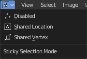
Disabled
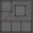
No sticky selection. You can just move one UV vertice at time. In case you have two vertices above each other, like with a UV patch with two faces, then just one vertice gets selected. Even when it's the same UV patch.
Shared Location
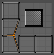
Selects all UV vertices under the mouse in case it's part of the same UV patch. Vertices of other UV patches gets ignored.
In this shot the two down left faces are one UV patch.
Shared Vertex
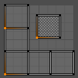
Selects all UV vertices that shares the same vertice at the 3D mesh. Regardless if it's the same UV patch or not.
UV Select Sync on

With UV Select Sync on you will keep selections of UV space and 3D view in sync. But you cannot modify single UV elements anymore. In this mode you work with Vertices, Edges and Faces.
All UV geometry of the object will show up, no matter what's selected in the 3D view.
You can switch between the selection modes with hotkeys 1, 2, 3. Note that this selection mode is in sync with the selection modes in the 3D view. When you change it in the one editor, then it changes in the other editor too.
Vertex selection mode
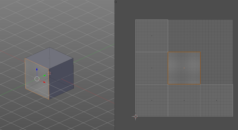
Select vertices in the UV geometry and at the 3D mesh object.
| Entry | What it does |
|---|---|
| Edge selection mode | Select edges in the UV geometry and at the 3D mesh object. |
| Face selection mode | Select single faces in the UV geometry and at the 3D mesh object. |
Header Tools and Options
UV Editor - Header Tools
The header contains several tools, dependent of what you do and what tool set is selected.

Pivot
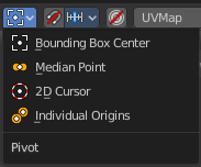
What pivot point to use for selected elements.
When you rotate or scale an UV patch, or a group of vertices/edges/faces, you may want to set the pivot point to a specific location of the selection. The names should be self explaining.
Snapping
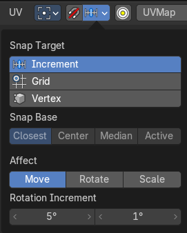
Activate snapping when transforming an element.
Snapping can be temporarily activated by holding Ctrl key. So no need to turn snapping on and off all the time.
| Entry | What it does |
|---|---|
| Snap Target | You can snap to various scene elements. This menu allows you to define to which other elements the current active element should snap to. The names should be self explaining. Increment snaps by a grid unit. · Snap Base: Just with method Vertex. To which element to snap. |
| Affect | Adjust what transform methods should be affected by snapping. |
| Rotation Increment | Snap in adjustable incremental steps. |
Proportional Editing
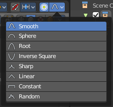
Enables proportional editing.
Proportional Editing is a way of transforming selected elements (such as vertices) while having that transformation affect other nearby elements with a falloff. For example, moving a single vertex will move unselected vertices within a given range. And the falloff means that selected vertices that are closer to the selected vertex will move more than those farther from it.
Settings
The settings appears when you activate Proportional Editing. Choose between different falloff methods for the proportional editing. The settings hides when proportional editing is off.
Proportional Size

When proportional editing is on then you will see a black circle around the selection that defines the influence area of the proportional editing.
This value can be adjusted with the scroll wheel, the page up and page down hotkeys, and in the last operator panel of the transform tools.
UV Map Property
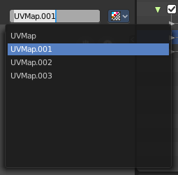
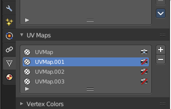
A mesh can have more than one UV map. You create them in the Properties editor in the Object Data Properties tab in the UV Map Panel.
The property in the header allows you to switch to another UV map, and to rename the UV map.
Image Prop

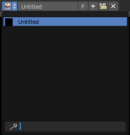
This property contains the list of loaded images. When no image is loaded then it displays the New and Open Buttons. When an image exists then it displays the name of the currently selected image.
From left to right ...

| Entry | What it does |
|---|---|
| List of images in the scene | This is a list of the images in the scene. This list allows you to switch to other images. · Search form: Search for specific images. |
| Image Edit Box | Read the name of the currently selected image. And you can rename the image here too. |
| Fake User | Wit this button you assign a fake user to this selected image. Data, like images, that is not longer linked to anything else gets removed when you save and reload a scene. Bforartists has the concept of fake users to go around this behavior. An image with a fake user is in fact linked to something. And so it is not lost when you save and reload the scene. |
| Open | Open a new image. |
Remove
Removes the image.
New Image
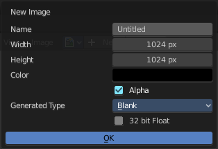
Create a new image.
Creates a new image. You will get a dialog where you can define settings for the new image.
| Entry | What it does |
|---|---|
| Name | The name of the new image |
| Width | The width of the new image. |
| Height | The height of the new image. |
Color
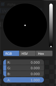
Adjust the color of the new image. A click will call a color picker.
Alpha
Check this checkbox if the new image should have an alpha channel.
Generated Type
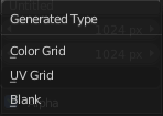
Here you can define what kind of texture you want to create.
Blank is one plain color.
UV Grid is a checker texture in black and white.
Color Grid is a colored checker texture.
32 Bit Float
Check this checkbox if the image should be in 32 Bit floating point bit depth per channel. Else it is in 8 bit per channel.
Duplicate
Not supported here.
Unlink Datablock
This deletes the selected image. Unfortunately not immediately. You need to save the scene and to reload it.
And you need to make sure that it is not linked to anything else. A mesh or a fake user for example. Have a look if there is a number besides the F button. When this is the case then the image has still a user, and so still loads with loading the scene.
| Entry | What it does |
|---|---|
| Fake User | Wit this button you assign a fake user to this selected image. Data, like images, that is not longer linked to anything else gets removed when you save and reload a scene. Bforartists has the concept of fake users to go around this behavior. An image with a fake user is in fact linked to something. And so it is not lost when you save and reload the scene. |
| Open Image | Opens the file browser to load an image. |
| Unpack | Unpack packed files to a directory. |
| User | The number of users that uses this data. Data with a user number of 0 will be removed with closing Bforartists. |
Use Image Pin

When you select another object. for UV mapping for example, then usually the connected images for this object gets displayed. Use image pin nails the currently selected image so that it stays displayed.
Show Gizmo
Show or hide the gizmos in the viewport
Show Overlays
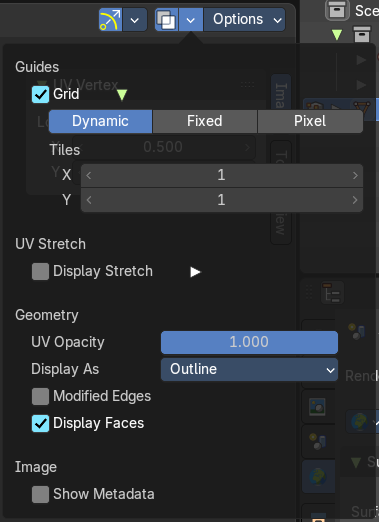
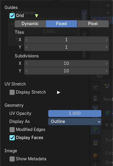

Guides
Grid
Display the ground grid.
Dynamic / Fixed / Pixel
Display the ground grid in defined resolution.
Dynamic adapts to the image size.
Fixed uses a fixed grid resolution. The method Fixed reveals x y edit boxes to set up the fixed resolution.
Pixel orients the grid size at the pixel resolution.
Grid over Image

Display the grid over the image. This prop just shows when an image is loaded.
Tiles
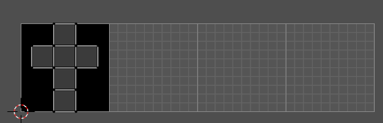
Display more tiles in the viewport than just the one in the 0-1 range. This is needed in conjunction with UDIM tiles.
Subdivisions
With method Fixed. Number of grid units in the UV space for one UV unit.
UV Stretch
Display Stretch
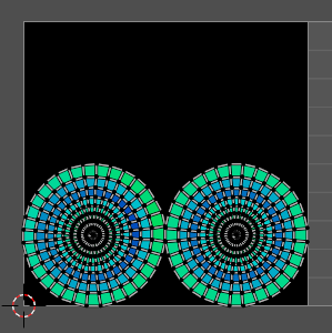
Display the uv mapping with different colors, dependant of the stretchiness of the uv mapped mesh. The different colors shows you how distorted the texture at the mesh is displayed. Blue is no stretching. Red is highly distorted stretching.
Display Stretch Type
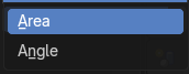
| Entry | What it does |
|---|---|
| Area | Calculates the stretch between UV and 3D faces. |
| Angle | Calculates the angular distortion between UV and 3D faces. |
Opacity
Opacity of the UV stretch overlay.
Geometry
UV Opacity
The opacity of faces in UV layer.
UV Opacity (in edit mode)
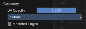
The opacity of the UV wireframe.
Display as
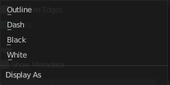
How to display the UV wireframe.
Modified Edges
Display the edges after the modifiers is applied. Else it shows the edges before the influence of the modifiers.
Image
Show Metadata
Display existing metadata in the viewport.
Display Channels
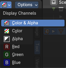
Adjust what channels of the image gets displayed. It just shows when an image is loaded and active.
| Entry | What it does |
|---|---|
| Color and Alpha | Displays the whole image, including alpha channel. |
| Color | Displays the whole image, but without alpha channel. |
| Alpha | Displays the alpha channel of the image. |
| Red | Displays the red channel of the image. |
| Green | Displays the green channel of the image. |
| Blue | Displays the blue channel of the image. |
Options Panel
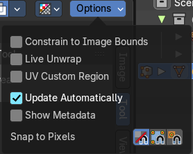
| Entry | What it does |
|---|---|
| Constrain to Image Bounds | Forces the UV geometry to stay within the image bounds when editing. Prevents UVs from being moved outside the image area (0–1 UV space). Useful for texture atlases and avoiding sampling errors. |
| Live Unwrap | Continuously unwrap the selected UV island while transforming pinned vertices. Automatically updates the UV layout when you transform geometry. Great for interactive editing, but can be performance-heavy on complex meshes. |
| Update Automatically | Update other editor windows simultaneously with the changes in the Image Editor. Refreshes the UV layout in real-time when changes occur. Keeps your view synced with modeling or shading edits. |
| UV Custom Region | This enables user-defined regions in the UV space (e.g. for packing or alignment). Pairs well with the Set User Region operator. |
| Show Metadata | Displays image metadata (resolution, color space, etc.) in the UV/Image Editor. Helpful for debugging texture issues or verifying file properties. |
Snap to Pixels
Snaps UV vertices to pixel boundaries of the image. Ideal for pixel art, low-res textures, or precise texel alignment.
- **Disabled: **Don’t snap to the nearest pixel.
- Corner: UV vertices snap to the nearest pixel corner.
- Center: UV vertices snap to the center of each pixel.
Quick Menu
Quick Menu
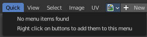
The quick menu, or in long Quick Favorites menu, is a menu that can be customized to your needs. Here you can add operators for quick access.
It is located in the header. But it can be called by hotkey Q directly under the mouse. This hotkey works in other editors too.
When the menu is empty, then you will see the message "No Menu Items found". This means that you first have to add some tools to the menu. It is a user configurable menu.
Note that added operators in this menu does not have icons. Just text.
Note also that the Quick menu for the UV editor shares the content with the Quick menu from the Image editor.
Adding an operator to the Quick menu
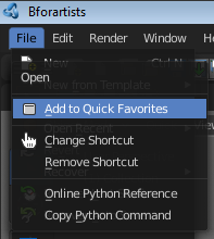
Open the panel or the menu where your operator is that you want to add.
Let's add the open command from the File menu. Open the File menu, right click at open, and choose Add to Quick Favorites.
Do the same with Save As. We should now have two new menu items in the Quick menu, which you can use now.
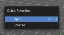
As a rule of thumb, when the right click menu has an Add to Quick Favorites, then you can add it to the quick menu.
Note that you can also add operators from the tool shelf at the left. And also operators from other editor types. Some other editors have their own quick menu though. The Image Editor for example. These operators gets added in the quick menu of the image editor then. And does not show in the quick menu in the header of the 3D view.
Adding a menu to the Quick menu
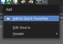
It is also possible to add a menu to the Quick menu. For example the whole Add menu. The way is the same. Right click at it, and choose Add to Quick Favorites.
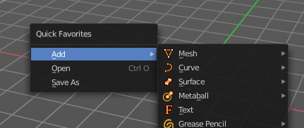
Order
You might notice that the add menu adds at the top of the menu, and not at the bottom as you would expect. First comes menus, then comes operators. And they get added in the order in which you add them.
Besides that, operators and menus gets added in the order that you add them. They cannot be sorted afterwards. So be careful how you add them. You can of course always remove operators and menus, and re-add them at the end of the list.
Removing an operator from the Quick menu
The Quick Favorites menu (Q) holds the tools and menus you add to it yourself. See Quick Favorites in the Interface chapter.
Context and mode dependent content
The quick favorites. menu exists in nearly all editors. But it is just in the 3D view available in the header. So that you know this functionality exists. In the other editors you call it with hotkey Q.
The content of the quick favorites. menu changes, dependent over which editor you are, and in what mode you are. When you add for example an operator from the image editor, then this operator just shows in the quick menu when you call the menu from the image editor. Same goes for the modes. Edit mode tools will just show in edit mode. And so on.
View Menu
Image Editor - View Menu
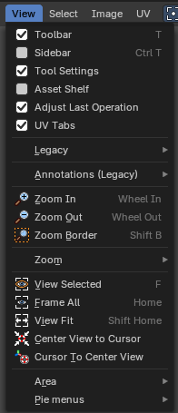
The View menu contains all View related tools.
Toolbar
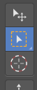
Shows or hides the tool shelf at the left.
Sidebar
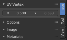
Shows or hides the sidebar at the right in the viewport
Tool Settings
Shows or hides the tool settings above the header in the 3D view.
Asset Shelf
Shows or hides the asset shelf at the bottom of the editor.
Adjust Last Operation - Image Editor - View Menu
Shows or hides the Adjust Last Operation panel down left.
Note that the Adjust Last Operation menu item in the Edit menu in the main header and the Last button in the toolbar are not related and not functional with this last operator panel. It is an independent element.
Tool Shelf Tabs
Show or hide the tabs in the tool shelf.
Legacy

Set 2D cursor
The old way to set the 2d cursor. Not by the tool shelf tool. Hotkey only tool! Please use the hotkey.
Annotations (Legacy)
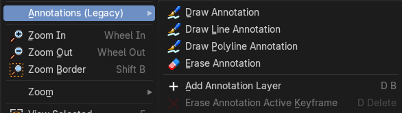
This group of operators is useful to take notes without changing tool-shelf operators. These notes can be colored in the View tab of the Property Shelf. Each layer is a single color. You can also animate the notes with keyframes, editable in the dopesheet.
Note: These are legacy operators, meaning they are equally available in the Toolshelf as a modal operator.
| Entry | What it does |
|---|---|
| Draw Annotation | Starts the annotation free hand draw tool in the editor. |
| Draw Line Annotation | Starts the annotation line draw tool to draw straight lines in the editor. |
| Draw Polyline Annotation | Starts the annotation Polyline draw tool in the editor which allows to draw multiple connected straight lines in the editor. |
| Erase Annotation | Starts the annotation erase tool in the editor which erases any strokes in the editor. |
| Add Annotation Layer | Starts a new annotation layer. |
| Erase Annotation Active Keyframe | Erases the active keyframe of the annotation. |
| Entry | What it does |
|---|---|
| Zoom In | Zooms into the viewport. |
| Zoom Out | Zooms out of the viewport. |
| Zoom Border | Draws a rectangle and zooms then to fit the size of this rectangle. Zooming in is done with drawing the rectangle with left mouse button. Zooming out is done with drawing the rectangle with middle mouse button. |
Zoom
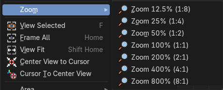
A sub menu where you can choose between predefined zoom factors.
| Entry | What it does |
|---|---|
| View Selected | View Selected centers the view at the currently selected UV mesh parts. |
| Frame All | View all zooms in or out in the viewport until all objects in the scene are displayed fitting in the viewport. |
| View Fit | Zooms out or in to fit the image to the viewport. |
| Center View to Cursor | Centers the view to the 2D cursor. |
| Cursor to Center View | Centers the cursor and the view to the center of the viewport. |
Area
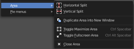
This menu contains general view functionality. And exists in most other editor types too.
| Entry | What it does |
|---|---|
| Horizontal Split | Splits the current view horizontally into two independent editor windows. |
| Vertical Split | Splits the current view vertically into two independent editor windows. |
Duplicate Area into New Window
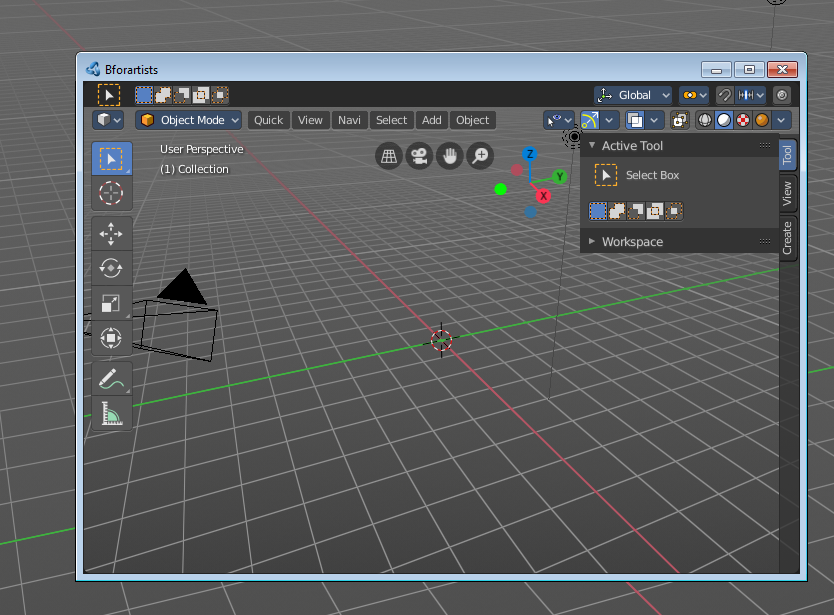
Duplicate Area into New Window opens this editor in a floating window. See Floating editor windows in the Interface chapter.
| Entry | What it does |
|---|---|
| Toggle Maximize Area | Displays the editor maximized with menus. To return from the maximized view press hotkey Ctrl + Space. Or reuse the menu item in the area menu. |
| Toggle Full screen Area | Displays the editor maximized without menus. To return from the full screen view press hotkey Ctrl + Alt + Space. |
| Close Area | Closes the editor. |
Pie menus
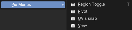
Lists the available pie menus, and gives you the ability to read the hotkeys and assign own hotkeys.
Select Menu
Select menu
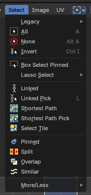
This menu just appears when you are in Mask mode. And you need to create a new mask layer to set all items active. The select functionality in this menu covers the mask geometry. The splines.
Legacy

The legacy sub menu contains tools that exists in the tool shelf already. It's the old way to do things. Different to the tools in the tool shelf, these tools are usually modal. And performs once. You have to call them again in case you want to repeat the tool.
| Entry | What it does |
|---|---|
| Box select | Draw a rectangle to select everything inside of the rectangle. It automatically adds to the current selection. Holding down shift subtracts from the selection. |
| Circle select | Brush select content. The radius of the brush can be adjusted by holding down left mouse button and using the scroll wheel or the + or - button at the numpad. It automatically adds to the current selection. Holding down shift subtracts from the selection. To exit the circle select tool click with the right mouse button. |
| Entry | What it does |
|---|---|
| All | Select everything. |
| None | Select nothing. |
| Inverse | Invert the current selection. |
Box Select Pinned
Box select enters the Border Select mode. This is a special select mode where you can select elements by dragging a rectangle. And what's inside of the rectangle gets selected then. It adds to selection by default. Box Select Pinned just selects pinned UV vertices. The other box select method can be found in the tool shelf.
To subtract from selection hold down Shift key.
The selection gets applied when you release the mouse. You leave the mode automatically when you release the mouse.
Lasso Select Submenu

The legacy lasso select tool. You can choose between three modes. Lasso select is also available in the tool shelf.
Linked
Selects everything linked to what you already have selected, so you get whole UV islands. The previous selection gets cleared.
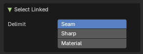
Last Operator Select Linked
| Entry | What it does |
|---|---|
| Delimit | Stop the selection at certain edges, so you only get part of an island. Seam: stop at UV seams. · Sharp: stop at edges marked sharp. · Material: stop where the material changes. Pick one or more, or none to select the whole island. |
Linked Pick
Note: Hotkey Only Tool!
Select all UV vertices linked to the active UV map. The previous selection gets cleared.
Adjust Last Operation - Select Linked Pick
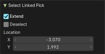
| Entry | What it does |
|---|---|
| Extend | The previous selection gets kept, the selection gets extended. |
| Deselect | Deselect instead of select |
| Location X / Y | The mouse position in the UV space, normalized to the 0.0 to 1.0 range of the UV space. |
| Delimit | Stop the selection at certain edges, so you only get part of an island. Seam: stop at UV seams. · Sharp: stop at edges marked sharp. · Material: stop where the material changes. Pick one or more, or none to select the whole island. |
Shortest Path
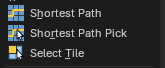
Selects a continuous path of UV elements (vertices, edges, or faces) between two points using the shortest route. Useful for isolating edge loops, seams, or structured selections across UV islands.
Adjust Last Operation - Shortest Path
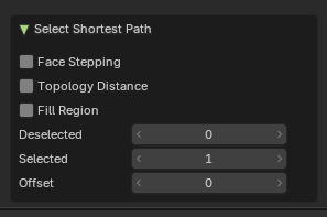
| Entry | What it does |
|---|---|
| Face Stepping | When enabled, selection prefers paths that follow face adjacency. Useful for maintaining logical flow across quads or structured meshes. |
| Topology Distance | Uses mesh topology rather than UV layout to determine the shortest path. Ideal for selections that mirror 3D geometry rather than UV spacing. |
| Fill Region | Expands the selection to include all elements of the UVs enclosed by the path. This will make a “patch” of the selection between the shortest bath. Useful for selecting entire UV islands or enclosed zones. |
| Deselected / Selected | Define how many elements are selected or deselected. An example is it will select 10 faces between face A and B, but it will deselect every second group of faces, and then select 2 faces as that group of faces. So it will select the first two, skip one, select another 2, skip one, and so forth. |
| Offset | Pushes the selected and unselected faces that have been interpolated between element A and B. Useful for nudging the path toward a specific direction or avoiding overlaps. |
Shortest Path Pick
Note: Best used as a Hotkey Only Tool!
Like the Shortest Path operator, this will select the shortest path under the mouse location between two selected elements.
Adjust Last Operation - Shortest Path
| Entry | What it does |
|---|---|
| Face Stepping | When enabled, selection prefers paths that follow face adjacency. Useful for maintaining logical flow across quads or structured meshes. |
| Topology Distance | Uses mesh topology rather than UV layout to determine the shortest path. Ideal for selections that mirror 3D geometry rather than UV spacing. |
| Fill Region | Expands the selection to include all elements of the UVs enclosed by the path. This will make a “patch” of the selection between the shortest bath. Useful for selecting entire UV islands or enclosed zones. |
| Deselected / Selected | Define how many elements are selected or deselected. An example is it will select 10 faces between face A and B, but it will deselect every second group of faces, and then select 2 faces as that group of faces. So it will select the first two, skip one, select another 2, skip one, and so forth. |
| Offset | Pushes the selected and unselected faces that have been interpolated between element A and B. Useful for nudging the path toward a specific direction or avoiding overlaps. |
Select Tile
Selects all UV elements (vertices, edges, or faces) that belong to a specific UDIM tile.
Useful for isolating texture regions, organizing UV layouts, or applying operations to targeted tiles in multi-tile workflows
Note: You need more than one UDIM tile to use this conveniently. To define UDIM tiles, add a new image with UDM tiles activated then use the Sidebar Image tab with the UDIM Tiles panel to add new tiles.
Adjust Last Operation - Select Tile
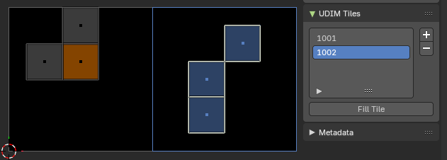
Extend
Checkbox that determines whether the selection adds to the current selection or replaces it.
- Enabled: selected tile UVs are added to the existing selection.
- Disabled: current selection is cleared before selecting the tile.
Tile
Two numeric fields representing the UDIM tile coordinates:
- U (horizontal): selects the tile column.
- V (vertical): selects the tile row.
| Entry | What it does |
|---|---|
| Pinned | Select pinned UV vertices. |
| Split | Select only entirely selected faces. |
Overlap
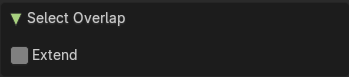
Select all UV faces that overlaps each other.
Adjust Last Operation - Select Overlap
Extend
Extend the current selection.
Similar

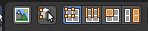
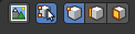
Similar selects similar elements to the already selected parts. It is mode dependant. When you are in Vertex mode, then it shows just a Vertex related menu. When you are in edge select mode, then a edge related menu. And when you are in face select mode, then a face related menu. And this for both, the UV sync selection off and on.
Pinned
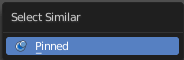
Select UV patches with pinned vertices.
Length
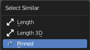
Select UV edges that has the same length in the UV Space.
Length 3D
Select UV edges that has the same length in the 3D View.
Area
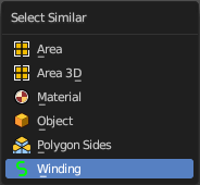
Select UV edges that has the same area in the UV Space.
| Entry | What it does |
|---|---|
| Area 3D | Select UV edges that has the same area in the 3D View. |
| Material | Select UV faces with the same material. |
| Object | Select UV faces at the same object. |
| Polygon Sides | Select UV faces that points into the same side in the 3D view. |
| Winding | Select UV faces in winding order. |
Amount of Faces
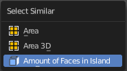
With UV Select Mode Islands. Selects all UV Islands with the same amount of faces.
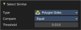
Adjust Last Operation - Select Similar
| Entry | What it does |
|---|---|
| Type | The select similar method. |
| Compare | Compare if the element to select should be greater, equal or less big than the current selection. |
| Threshold | A tolerance setting. |
Shortest Path
Select the shortest path between two selected elements.
Note that shortest path is a hotkey tool. Select the first element, hold down ctrl, select the second element.
Adjust Last Operation - Pick Shortest Path
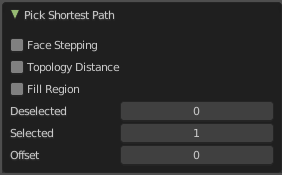
Face Stepping
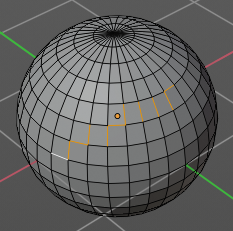
Traverse connected faces.
Topology Distance
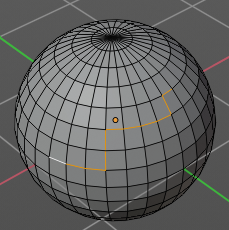
Find the minimum number of steps instead of the shortest distance.
Fill Region
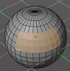
Select the region faces too.
Nth Element
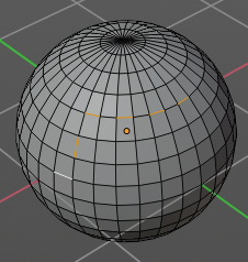
Don't select the whole path, but just every nth element of it.
| Entry | What it does |
|---|---|
| Skip | This is connected to nth element. Number of elements to skip at once. |
| Offset | This is connected to nth element. Start with an offset. |
More / Less submenu
| Entry | What it does |
|---|---|
| More | Grow the selection. |
| Less | Shrink the selection. |
Image Menu
UV Editor - Image Menu
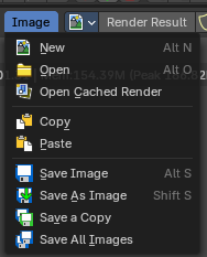
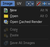
The Image menu contains the load and save functionality.
Not all content shows with all image types. A Render Result shows a different menu content.
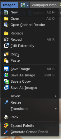
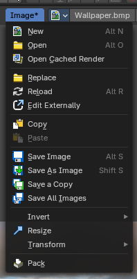
New
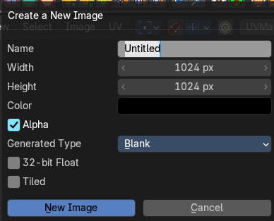
Creates a new image. You will get a dialog where you can define settings for the new image.
| Entry | What it does |
|---|---|
| Name | The name of the new image |
| Width | The width of the new image. |
| Height | The height of the new image. |
Color
Adjust the color of the new image. A click will call a color picker.
Alpha
Check this checkbox if the new image should have an alpha channel.
Generated Type
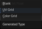
Define what kind of texture you want to create.
Blank is one plain color.
UV Grid is a checker texture in black and white.
Color Grid is a colored checker texture.
| Entry | What it does |
|---|---|
| 32 Bit Float | Check this checkbox if the image should be in 32 Bit floating point bit depth per channel. Else it is in 8 bit per channel. |
| Tiled | Create a tiled image. |
Open
Opens the file browser to load an image.
Open Cached Render
To get it to work you need to have Cycles as the renderer selected. This feature does not work with Eevee or Workbench renderer.
Read all the current scene's render layers from cache, as needed.
This feature can be be used to save RAM while rendering because the render layers do not have to be saved in RAM. It can also be used to recover some information from a fail render.
| Entry | What it does |
|---|---|
| Replace | Replaces the currently active image by an image that you load. |
| Reload | Reloads the currently selected image. Note that the images must already exist somewhere at your hard disk. When you create a new image in Bforartists, then this image isn't saved yet, and so you cannot reload it. |
| Edit Externally | Open the image in a defined external image editor like The Gimp or Photoshop. The image must be saved. And the image editor must be defined in the User Preferences. |
| Save Image | Saves the currently selected image without any further questions. Note that the images must already exist somewhere at your hard disk. |
| Save As Image | Saves the currently selected image. |
| Save a Copy | Saves a copy of the currently selected image. This will save the file to a specified name, but will keep the old one open in the Image editor. |
| Save all Images | Saves all images. Note that the images must already exist somewhere at your hard disk so that they can be saved. The item is greyed out as long as the image is not saved to disk. |
Invert submenu
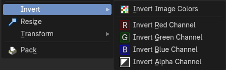
Invert is a sub menu where you can invert the colors of the whole image, or just specific colors.
Note: This only shows when in the when not viewing the Viewer or Render Result.
Resize
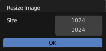
Allows you to change the dimensions of the image. The tool calls a resize panel.
Note: This only shows when in the when not viewing the Viewer or Render Result.
Transform submenu
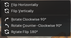
Note: These only shows when in the when not viewing the Viewer or Render Result.
| Entry | What it does |
|---|---|
| Flip Horizontally | Flip the image horizontally around it’s central axis. |
| Flip Vertically | Flip the image vertically around it’s central axis. |
| Rotate Clockwise 90° | Rotate the image to the right by 90 degrees. |
| Rotate Counter-Clockwise 90° | Rotate the image to the left by 90 degrees. |
| Rotate Flip 180° | Rotate the image to the right by 180 degrees and flip the image upside down. |
Pack

Packs the currently active image into the blend file. When you save the blend file the next time, then this image will be embedded. The Pack menu item turns into an Unpack menu item with packed textures.

Packed images are marked with a pack icon. A click at this icon will unpack the texture, and try to save it to file. Usually to the last existing location before it was packed.
Warning: You cannot modify packed images. Changes at the image will not be saved. You need to unpack the image when you want to modify it. And repack it after you have done the changes.
UV Menu
UV menu
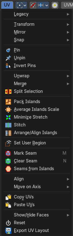
The UV header menu contains all the UV related operators in the UV Editor.
Legacy

UV Rip Move
This “cuts” the selection from the island so you can then move it. This can also be accessed by the modal operator in the tool shelf.
Transform
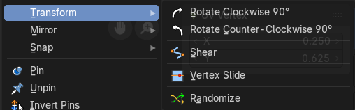
Rotate Clockwise 90°
Rotates the selection by 90 degree clockwise.
Rotate Counter Clockwise 90°
Rotates the selection by 90 degree counter clockwise.
Adjust Last Operation - Rotate
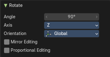
| Entry | What it does |
|---|---|
| Angle | The rotation angle. |
| Axis | Defines one axis of the imaginary shear axis plane. |
Orientation
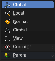
Choose the orientation for the shear action.
| Entry | What it does |
|---|---|
| Mirror Editing | Enable mirror editing. |
| Proportional editing | Enables proportional editing. Activating proportional editing reveals further settings. · Proportional Falloff: Adjust the falloff methods. · Proportional Size: See and adjust the falloff radius. · Connected: The proportional falloff gets calculated for connected parts only. · Projected(2D): The proportional falloff gets calculated in the screen space. Depth doesn't play a role. When it's in the radius, then it gets calculated. |
Shear
Shear shears the selection.
Adjust Last Operation - Shear
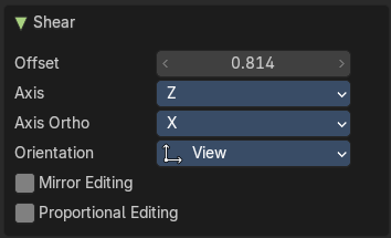
| Entry | What it does |
|---|---|
| Offset | Adjust an offset. |
| Axis | Defines one axis of the imaginary shear axis plane. |
Axis Ortho
Defines the other axis of the imaginary shear axis plane.
| Entry | What it does |
|---|---|
| Orientation | Choose the orientation for the shear action. |
| Mirror Editing | Enable mirror editing. |
| Proportional editing | Enables proportional editing. Activating proportional editing reveals further settings. · Proportional Falloff: Adjust the falloff methods. · Proportional Size: See and adjust the falloff radius. · Connected: The proportional falloff gets calculated for connected parts only. · Projected(2D): The proportional falloff gets calculated in the screen space. Depth doesn't play a role. When it's in the radius, then it gets calculated. |
Vertex Slide
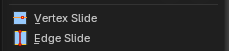
Slide a vertex along the parent edge of the mesh UV.
Note: This is exclusively a vertex selection mode operator.
Adjust Last Operation - Vertex Slide
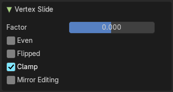
| Entry | What it does |
|---|---|
| Factor | The factor of the slide, moving the selection in a positive or negative direction from starting position. |
| Even | Make the edge loop match the shape of the adjacent edge loop. |
| Flipped | When Even mode is active, this will flip between the two adjacent edge loops |
| Clamp | Clamp within the edge constraints. |
| Mirror Editing | Edit it in mirror mode. |
Edge Slide
Slide an edge along the adjacent edges of the mesh UV.
Note: This is exclusively an edge selection mode operator.
Adjust Last Operation - Edge Slide
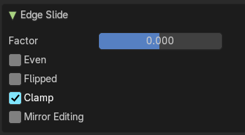
| Entry | What it does |
|---|---|
| Factor | The factor of the slide, moving the selection in a positive or negative direction from starting position. |
| Even | Make the edge loop match the shape of the adjacent edge loop. |
| Flipped | When Even mode is active, this will flip between the two adjacent edge loops |
| Clamp | Clamp within the edge constraints. |
| Mirror Editing | Edit it in mirror mode. |
Randomize
Adjust Last Operation - Randomize
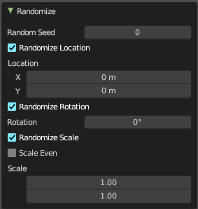
| Entry | What it does |
|---|---|
| Random Seed | The seed for the randomization. |
| Randomize Location | Randomize the location values. |
| Location | The maximum distance the objects can spread over each axis. |
| Randomize Rotation | Randomize the rotation values. |
| Rotation | The maximum allowed rotation |
| Randomize Scale | Randomize the scale values. |
| Scale Even | Randomize the scale values. |
| Scale | The maximum scale the objects can scale over each axis. |
Mirror
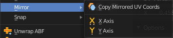
Copy Mirrored UV coords
Copies and pastes the selected UV geometry on the X axis based on a mirrored mesh.
Use UV Select Sync must be off. The tool does not work with Use UV Select Sync on. And it is not fully reliable as our example shows.
Adjust Last Operation - Copy Mirrored UV Coords
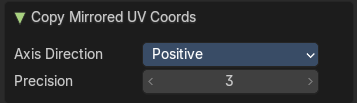
Axis Direction
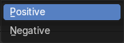
The axis direction.
Precision
Tolerance for finding vertex duplicates.
X
Mirrors the selection in X axis. The mirror point is the pivot of the selection.
Y
Mirrors the selection in Y axis. The mirror point is the pivot of the selection.
Adjust Last Operation - Mirror X Y Z Global
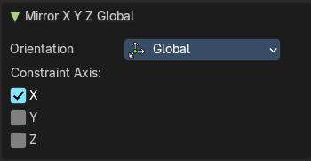
The Last Operator Mirror panel gives you tools to adjust the mirror action.
Orientation
Orientation is a drop-down box to choose the type of orientation for the mirroring action.
Constraint Axis
Constraint Axis gives you the possibility to define the mirror axis. You can choose more than one axis here.
Snap
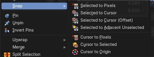
Snap is a sub menu with some snapping tools. The menu items should be pretty self explaining. Selected to Pixels snaps the selected geometry to the pixels of the image, and so on.
Adjust Last Operation - Snap Selection and Snap Cursor
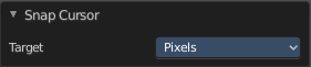
Target
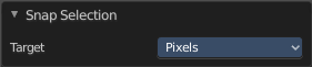
Set the snap target method again.
Pin
Pins the selected vertices . This vertices are now nailed for the unwrap algorithms Angle based and Conformal. Their positions will not change when you repeat the unwrapping. And the algorithms will try to fit the rest of the geometry to this pinned vertices.
Pinned vertices are marked red.
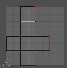
A use case is for example when you have a distorted result for symmetric geometry like a face with the Conformal method. Then you can try to align two center vertices, pin them, and repeat the conformal method. It may be more symmetrical afterwards.
Unpin
Unpins pinned geometry.
Invert Pins
This operator inverts the pins to all selected pins, and unpins the set pins. This will only work if you have geometry selected.
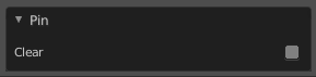
Adjust Last Operation - Pin
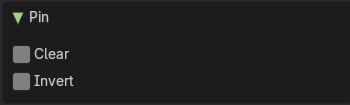
This last operator appears in the 3D view to the bottom left of the editor. Pin, Unpin and Invert Pins shares the same last operator.
| Entry | What it does |
|---|---|
| Clear | Unpins pinned geometry. |
| Invert | Inverts the pinned geometry to selected geometry, and unpins the set pins. |
Unwrap
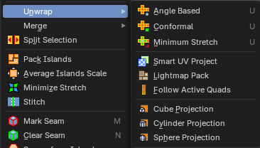
| Entry | What it does |
|---|---|
| Angle Based | Unwraps the selected geometry with the method Angle based. ABF stands for Angle Based Flattening. ABF can give a bit better result than LSCM when unwrapping organic shapes. |
| Conformal | Unwraps the selected geometry with the method LSCM, which is the short for Least Square Conformal Mapping. LSCM can give a bit better results than ABF with geometric shapes. |
| Minimum Stretch | Unwraps the selected geometry with the method SLIM, which is a “state-of-the-art” iterative UV unwrapping algorithm. |
Adjust Last Operation - Unwrap
Method
Method is a drop down box where you can choose the unwrap method.
Method Angle based + Conformal
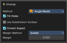
Unwrap ABF and Unwrap LSCM shares the same Last Operator.
Method
Method is a drop down box where you can choose between Unwrap method Angle Based and Conformal.
Fill Holes
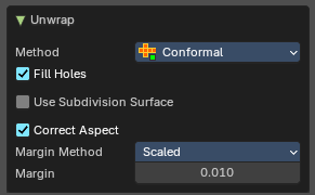
Fill holes in the mesh before unwrapping.
| Entry | What it does |
|---|---|
| Use Subdivision Surface | Unwraps an existing Subdivision Modifier. You need to add a Subdivision Modifier first. |
| Correct Aspect | Take the Image Aspect Ratio into account. |
Margin Method
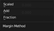
| Entry | What it does |
|---|---|
| Scaled | Use the scale of existing UV to multiply margin. |
| Add | Just add the margin and ignore any existing UV. |
| Fraction | Specify a precise fraction of specific UV. |
Margin
The distance between the single UV patches.
Method Minimum Stretch
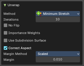
Iterations
Number of iterations.
| Entry | What it does |
|---|---|
| No Flip | Prevent flipping UV's |
| Importance Weight | Take per vertex importance weights into account. |
| Use Subdivision Surface | Unwraps an existing Subdivision Modifier. You need to add a Subdivision Modifier first. |
| Correct Aspect | Take the Image Aspect Ratio into account. |
Margin Method
| Entry | What it does |
|---|---|
| Scaled | Use the scale of existing UV to multiply margin. |
| Add | Just add the margin and ignore any existing UV. |
| Fraction | Specify a precise fraction of specific UV. |
Margin
The distance between the single UV patches.
Smart UV Project
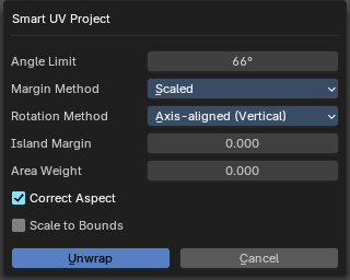
Smart UV Project projects the UV mapping from different angles.
Smart UV Project Settings dialogue
Angle Limit
The Angle Limit defines after which angle the mapping happens from the next side. With an angle of 66 you have around six sides to map from. The calculation is 360/66.
Margin Method
| Entry | What it does |
|---|---|
| Scaled | Use the scale of existing UV to multiply margin. |
| Add | Just add the margin and ignore any existing UV. |
| Fraction | Specify a precise fraction of specific UV. |
Rotation Method
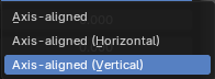
How to rotate islands.
| Entry | What it does |
|---|---|
| Island Margin | Island Margin defines the distance between the UV patches. |
| Area Weight | Weight Projection Vector by faces with larger areas. |
| Correct Aspect | Take the Image Aspect Ratio into account. |
Adjust Last Operation - Smart UV Project
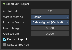
The Last Operator for Smart UV Project contains the same settings than the Smart UV Project Settings dialogue.
Lightmap Pack
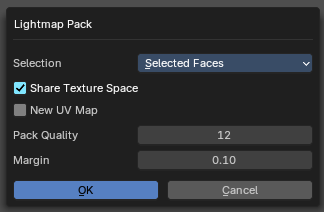
Lightmap Pack maps each face individually, and puts the result into the UV space. Without margin.
Lightmap Pack has no Last Operator.
Settings
| Entry | What it does |
|---|---|
| Selection | Selection is a drop-down box where you can choose what will be packed. |
| Share Tex Space | Map all objects into one lightmap. |
| New UV Map | Create a new UV map for every new mesh. |
| Pack Quality | The pack quality. |
| Margin | The distance between the single UV patches. |
Follow Active Quads
Follow Active quads maps UV coordinates starting from an active face, and maps all adjacent faces in quad shape then. This way you can for example unwrap a pipe or a road. You first need to have a face selected. Then select everything. And then click at Follow Active Quads.
Settings
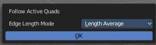
Edge Length Mode
Edge Length Mode is a drop-down box where you can choose the Length method.
Adjust Last Operation - Follow Active Quads
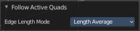
The Last Operator contains the same settings than the Settings dialogue.
Cube Projection
Cube Projection maps the mesh from six sides, means cubic.
Adjust Last Operation - Cube Projection
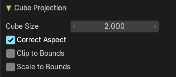
| Entry | What it does |
|---|---|
| Cube Size | Cube Size defines the size of the UV mesh in the UV space. |
| Correct Aspect | Take Image Aspect ratio into account. |
| Clip to Bounds | Clip UV Coordinates to bounds after unwrapping. |
| Scale to Bounds | Scale UV Coordinates to bounds after unwrapping. |
Cylinder Projection
Cylinder Projection tries to map the geometry cylindric.
Adjust Last Operation - Cylinder Projection
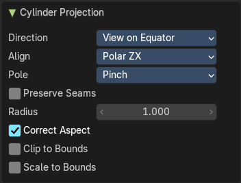
| Entry | What it does |
|---|---|
| Direction | Direction is a drop-down box where you can choose in which direction the cylindric projection will be mapped. |
| Align | Align is a drop-down box where you can choose the Align method. |
| Pole | How to handle the faces at the poles. |
| Preserve Seams | Separate Projections by islands isolated by seams. |
| Radius | Radius defines the Polar size of the UV mesh in the UV space. |
| Correct Aspect | Take Image Aspect ratio into account. |
| Clip to Bounds | Clip UV Coordinates to bounds after unwrapping. |
| Scale to Bounds | Scale UV Coordinates to bounds after unwrapping. |
Sphere Projection
Sphere Projection tries to map the geometry spherical.
Adjust Last Operation - Sphere Projection
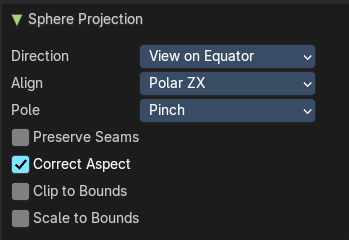
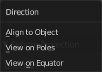
Direction
Direction is a drop-down box where you can choose in which direction the spherical projection will be mapped.
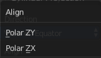
Align
Align is a drop-down box where you can choose the Align method.
| Entry | What it does |
|---|---|
| Pole | How to handle the faces at the poles. |
| Preserve Seams | Separate Projections by islands isolated by seams. |
| Correct Aspect | Take Image Aspect ratio into account. |
Clip to Bounds
Clip UV Coordinates to bounds after unwrapping.
Scale to Bounds
Scale UV Coordinates to bounds after unwrapping.
Merge
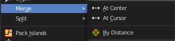
At Center
Merges the selected vertices at the center point.
At Cursor
Merges the selected vertices not only at the cursor. The last operator provides you with four methods.
Adjust Last Operation - Snap Selection
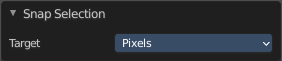
Target
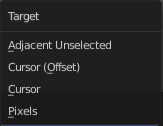
The snapping target. Snap and merge at the following locations.
Adjacent unselected
Cursor ( Offset)
Cursor
Pixels
By Distance
Merge UV vertices when they are below a merge distance.
Adjust Last Operation - Merge UV's by Distance

| Entry | What it does |
|---|---|
| Merge Distance | The merge distance below the vertices gets merged. |
| Unselected | Merge selected vertices to unselected vertices. |
| Shared Vertex | Weld UV’s based on shared vertices. |
Split Selection
Splits the selected geometry. UV Sync Selection needs to be off.
Pack Islands
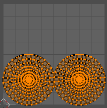
Pack Islands tries to pack the selected UV geometry as close together as possible. Without to waste too much empty space.
Note that the algorithm fails at round geometry. It calculates with rectangle shapes.
Pack Islands Popup
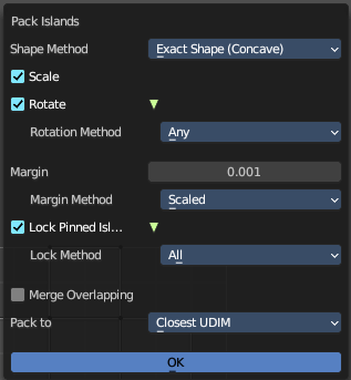
When you click the operator then you will see a popup panel where you can adjust the further settings.
Shape Method
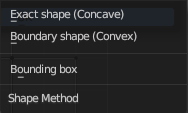
How the islands are packed.
| Entry | What it does |
|---|---|
| Exact Shape (Concave) | Use exact geometry. |
| Boundary Shape (Convex) | Use a convex hull. |
| Bounding Box | Use a bounding box. |
Scale
Scale islands to fill the unit square.
Rotate
Rotate islands to improve layout.
Rotation Method
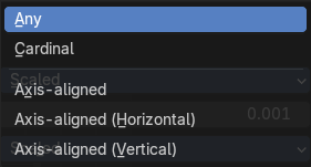
The rotation method.
| Entry | What it does |
|---|---|
| Any | Any angle is allowed for rotation. |
| Cardinal | Only 90 degrees rotation are allowed |
| Axis - aligned | Rotate to a minimal rectangle. Either horizontal or vertical towards the shortest distance. |
| Axis - aligned ( Horizontal ) | Rotate to a minimal rectangle. Horizontal. |
| Axis - aligned ( Vertical ) | Rotate to a minimal rectangle. Vertical. |
Margin
Adjust the margin amound.
Margin Method
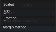
What method to use for the margin. UV patches needs a margin between the single patches. So that the pixels of the texture doesn't bleed into other areas.
Scaled
Use scale of existing UV's to multiply margin.
Add
Just add the margin. And don't use the UV scale for calculation too.
Fraction
Specify a precise fraction of final UV output.
Lock Pinned Islands
Constrain islands that contains any pinned UV's
Lock Method
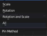
How to deal with pinned UV islands.
| Entry | What it does |
|---|---|
| Scale | Pinned islands won't scale. |
| Rotation | Pinned islands won't rotate. |
| Rotation and Scale | Pinned islands won't scale and rotate |
| All | Pinned islands will remain at their initial position and are locked in place. |
Merge Overlapping
Overlapping islands stick together.
Pack To
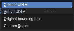
| Entry | What it does |
|---|---|
| Closest Udim | Pack islands to closest UDIM image tile |
| Active Udim | Pack islands to active UDIM image tile, or to the UDIM grid tile where the 2d cursor is located. |
| Original Bounding Box | Pack to the starting bounding box of islands. |
| Custom Region | Pack to custom region. |
Average Island Scale
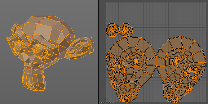
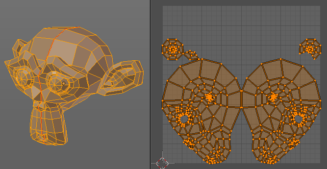
Scales the selected UV geometry to have the same relative size than the rest of the mesh. So that the texels at the mesh have roughly the same size everywhere.
Minimize Stretch
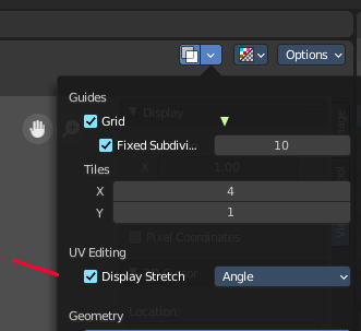
You might end in a UV mapping result that still shows unwanted distortions here and there. For example when you UV map a human face. Minimize Stretch tries to minimize this stretching effects in the UV patches.
To view stretched areas at your UV patches, tick Display Stretch in the Overlays panel, and switch from Angle to Area. Then a stretch mask gets displayed. The color range goes from blue to green to red, where blue is minimal stretch and red is maximal stretch.
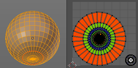
Let's explain it with an example. A sphere where the cut is nearly at the pole. And UV mapped with Angle Based. The result will of course show heavy stretched areas.
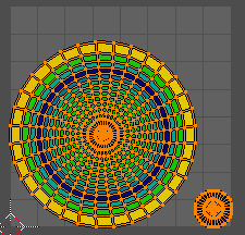
Note that the UV geometry must be selected in the UV Image editor. Now let's use the Minimize stretch tool. The algorithm now first tries its best to find the best fitting result that shows fewest stretching across the overall UV geometry.

The header shows a help text while the algorithm works. The Blend factor is the value between the original unwrapped UV mesh, and the maximum minimized stretch. You can set this value manually by using the scroll wheel at your mouse, or with the + and - keys.
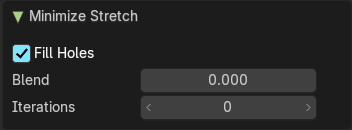
Adjust Last Operation - Minimize Stretch
| Entry | What it does |
|---|---|
| Fill Holes | Fill holes virtually fills holes before unwrapping to avoid overlapping and to preserve the geometry. |
| Blend | The Blend factor is the value between the original and the maximum minimized stretch. |
| Iterations | Number of iterations for the Minimize stretch algorithm. |
Stitch
Stitch tries to union UV patches along the selected edges or vertices.
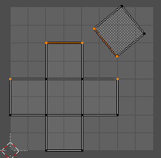
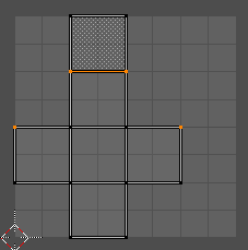
Adjust Last Operation - Stitch
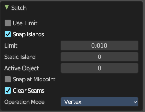
This last operator appears in the 3D view.
| Entry | What it does |
|---|---|
| Use Limit | Just snap when the elements are below a given distance. · Snap Island: Snap the whole UV patch, or just the selected edge(s)/vertices |
| Limit | The limit distance for Use Limit. |
| Static Island | Adjust which island stays in place when stitching. |
| Active Object | Index of the active object. |
| Snap at Midpoint | Snap at the center point of the two elements instead the first to the last. |
| Clear Seams | Unmarks seams when stitching. |
Operation Mode
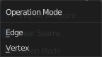
The operation mode. Calculate with Edges or Vertices.
Mark Seam
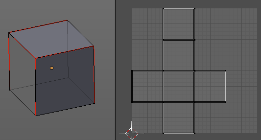
The unwrap algorithms Angle based and Conformal requires to have edges marked as seams. Think of it as a cutting pattern for a trouser for example. Such a trouser is also made of fabric patterns.
Same goes for the UV patches when you use Angle based or conformal unwrapping. You need to cut your mesh into parts and mark edges as seams, so that the algorithm knows where the seams are.
Mark seam marks the currently selected edge(s) as a seam. Seam edges will be displayed as red in the 3D viewport. But not in the UV Image Editor. The UV patches represents the seams.
You need to unwrap the mesh again when you want to apply changes by the new marked seams.
Adjust Last Operation - Mark Seam
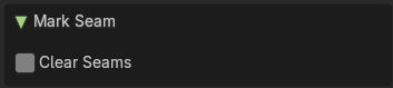
Clear
Clears the seam instead of marking it.
Clear Seam
Clear seam removes the seam from the currently selected edge(s) in the 3D view.
Seams from Islands
Unwrapping creates the UV geometry from the 3D object. You mark the seams, then you click at unwrap, and the UV mesh gets created.
Mark Seams from islands goes the other way around for marking seams. It creates the seams at the mesh object in the 3D view from the UV geometry in the UV Image Editor.
A use case is when you import meshes. Then you usually just have the UV patches in the UV Image editor. And when you want to modify the UV's further, then you need the seams at the mesh.
Align/Arrange Islands
Provides a unified interface for aligning, distributing, and organizing UV islands based on axis, order, and spacing. Ideal for texture atlases, modular layouts, and precision packing.
Aligns selected UV islands along a chosen axis.
Adjust Last Operation - Arrange/Align Islands
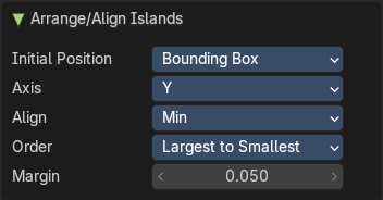
Initial Position
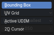
Defines how the alignment reference is calculated for each island. This determines where each island "snaps" during alignment—e.g., top edge, center, or bottom edge.
| Entry | What it does |
|---|---|
| Bounding Box | Uses the outer bounds of each island. |
| UV Grid | Aligns islands relative to the overall UV grid (typically 0–1 space). |
| Active UDIM | Uses the currently active UDIM tile as the reference. |
| 2D Cursor | Aligns islands based on the position of the UV Editor’s 2D cursor. |
Axis
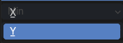
Specifies the direction along which islands will be aligned. X or Y. Useful for stacking islands top-to-bottom or side-by-side.
Align
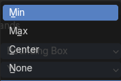
Controls which part of the island is aligned to the axis. This affects how islands are visually positioned relative to each other.
| Entry | What it does |
|---|---|
| Min | Aligns the minimum bound (e.g., bottom or left edge) |
| Center | Aligns the center of the island |
| Max | Aligns the maximum bound (e.g., top or right edge) |
| None | Preserves the island alignment. |
Order
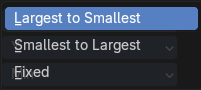
Determines the sequence in which islands are arranged.
Margin
Sets the spacing between islands after alignment. Adds consistent padding between islands to avoid texture bleeding or overlap.
Value
Float input (e.g., 0.050)
Set User Region
Defines a custom region within the UV Editor viewport, allowing you to isolate, focus, or constrain operations to a specific area of the UV space.
Use
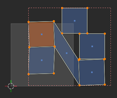
An example is for Packing Islands: Limit packing to a specific region (e.g. top-right quadrant of the UV space). This can be used to constrain packing or alignment operations.
This can also serve as a reference zone for manual editing or snapping.
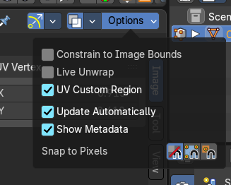
To toggle visibility after defining it manually, use the Options drop down to the top right of the header.
Align submenu
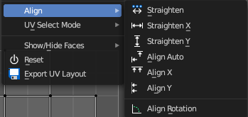
Align the selected geometry. Affected are the vertices.
| Entry | What it does |
|---|---|
| Straighten | Straightens the selected geometry in both directions, X and Y axis. |
| Straighten X | Straightens the selected geometry along the X axis. |
| Straighten Y | Straightens the selected geometry along the Y axis. |
| Align Auto | Aligns the selection. The align axis gets chosen from the selection itself. When it's higher than tall, then it aligns along the Y axis. When it's taller than high, then it aligns along the X axis. The align point is the pivot of the selection. |
| Align X | Aligns the selection along the X axis. The align point is the pivot of the selection. |
Align Y
Aligns the selection along the Y axis. The align point is the pivot of the selection.
Adjust Last Operation - Align
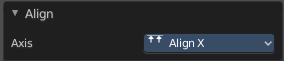
The Last operator Align unions all the single straighten and align actions in one operator.
Axis
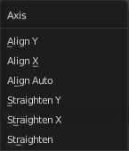
Lists the straighten and align methods again.
Align Rotation
Aligns the selected geometry horizontally or vertically. It aligns to the closest angle.
Adjust Last Operation - Align Rotation
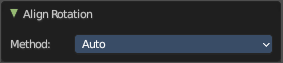
Method
Geometry
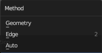
Aligns the whole geometry.
Edge
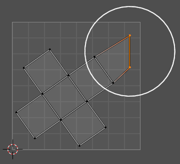
Aligns the geometry along the selected edge.
Auto
Checks for selection, and aligns then either the whole geometry or by the selected edge.
Move on Axis submenu

| Entry | What it does |
|---|---|
| Dynamic | Move UV’s on an axis dynamically |
| Pixel | Move UV’s on an axis by pixel |
| UDIM | Move UV’s on an axis by UDIM tile. |
| Entry | What it does |
|---|---|
| Copy UV | Copy selected UV vertices. |
| Paste UV | Pastes copied UV vertices. |
Show / Hide Faces submenu

Show or hide faces. This happens in both, the 3D View and the UV editor.
| Entry | What it does |
|---|---|
| Reveal Hidden | Makes all geometry visible again. |
| Hide Selected | Hides the selected geometry. |
| Hide Unselected | Hides the not selected geometry. The selected geometry stays visible. |
Adjust Last Operation - Reveal Hidden / Hide Selected
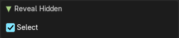
Select
Define if the selected or the unselected elements gets hidden or revealed.
Reset
Resets the UV projection. Every single face gets fit into the UV space range of 0/1
Export UV Layout
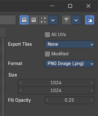
Export the UV layout to an image, so that you can use it as a mask to build your texture in your favorite image editing software like Photoshop. It will open a file dialog, where you can define further export settings down left.
In the export dialog you will see export settings at the right side
All UV's
Export all UV's, not just the visible ones.
Export Tiles
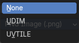
If to export UDIM tiles.
Modified
Export UV's from the modified mesh.
Format
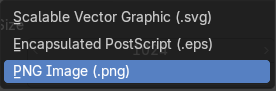
Choose the export format.
| Entry | What it does |
|---|---|
| Size | Define the size of the image. |
| Fill Opacity | How opaque the wire frame lines are. |