











































Utilities
Utilities nodes: Math, Text, Vector, Bundle, Closure, Field….
Add menu - Utilities
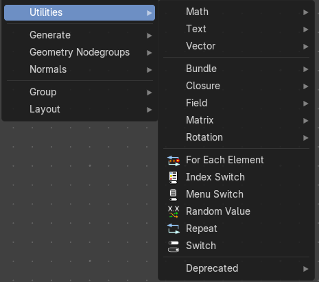
Utility nodes are mainly for mathematical operations with fields, values and elements.
For Each Element
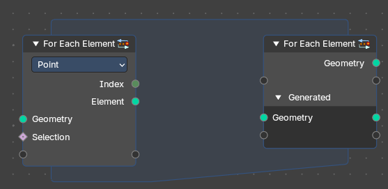
The For Each Element Node enables iterative operations on individual elements of a geometry. This node is ideal for tasks requiring unique processing for each element, such as creating distinct objects or attributes for every element: a face, vertex, or curve or other domain.
Note: The For Each Element Node is best for creating detailed or complex geometry for every element of an input. For instance, you can use it to generate a unique tree for each curve or a distinct building on every face of a mesh.
However, it's less efficient for handling tiny elements, like individual strands of hair. Processing small parts separately can slow things down because Blender isn’t able to optimize the operation effectively. For projects with many elements, it's better to design your node setup to avoid working on very small pieces one at a time. In this case, it is best to run operations directly on field domains.
For Each Element Input
Inputs
Geometry
The input geometry whose elements will be processed individually. This can include meshes, curves, or other geometry types.
Selection
Specifies which subset of elements to process. This allows filtering based on boolean attributes or conditions per field – typically used as a true/false mask.
Properties
Element
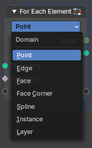
Defines which element of which domain will be used.
The input geometry is divided into individual geometries, each corresponding to a single element. During each iteration, the node processes one of these single-element geometries.
Note: However, this functionality does not apply to the Face Corner domain, as face corners are inherently tied to their parent face and cannot exist independently.
Output
Index
Provides the Index integer of the current elements of the selected domain to be processed.
Element
Returns a Geometry output with the list of elements for iteration.
For Each Element Output
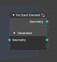
Inputs
Main Geometry
The Main Geometry outputs create attributes on the "main" output geometry (the first output). Each value calculated within the zone becomes part of the attribute at the corresponding index of this output.
Note: Default is blank.
Generated
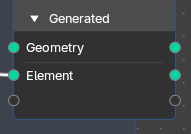
Result of joining generated geometries from each iteration.
The Generated inputs contain the individual geometry elements processed inside the zone. This includes any fields and attributes from different domains associated with these elements.
Note: Default is the result of joining generated geometries for each iteration.* *You can connect any new attribute or filed and output new generated elements and custom fields from the zone.
Properties
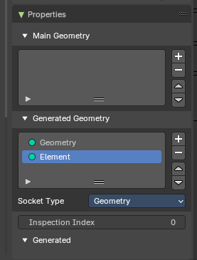
Main Geometry
The main geometry sockets.
Generated Geometry
The generated geometry sockets from the zone.
Socket Type
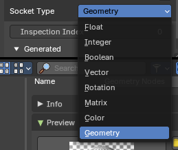
What input input and output socket type to evaluate from each iteration in the zone.
Inspection Index
Iteration index that is used by inspection features like the viewer node or socket inspection
Output
Geometry
The original input geometry with potentially new attributes that are output by the zone.
Element
Result of joining generated geometries or attributes from each iteration.
Index Switch
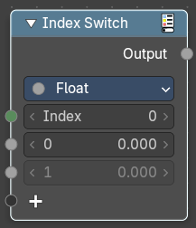
The Index Switch node is meant as a simpler version of the Menu Switch node. It doesn't allow naming items or displaying them in a dropdown, but still allows choosing between an arbitrary number of items, unlike the regular Switch node where you can just switch between two states.
Inputs
Index
Data type: Integer.
Wich input to choose.
0 , 1 ...
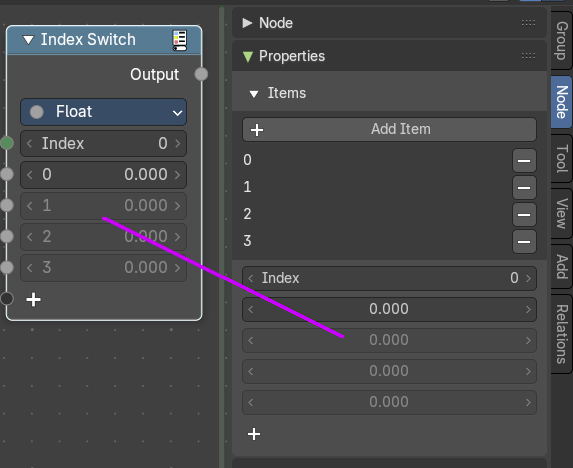
The available input index types that you want to switch between. You can define more input sockets in the sidebar.
Properties
Data Type
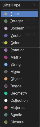
What input type to evaluate.
Outputs
Output
Data type: follows the Data Type setting.
The output index.
Menu Switch
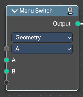
The Menu Switch node selects and computes one input based on a user-defined menu. Only the selected input is computed.
Menu entries can be added, removed, renamed, and reordered. Renaming keeps existing input links.
The menu can be used in node groups and the nodes modifier UI. Connecting the menu to a Group Input node exposes it as a group input. A menu needs to be connected to a Menu Switch node to work. An unconnected menu is empty.
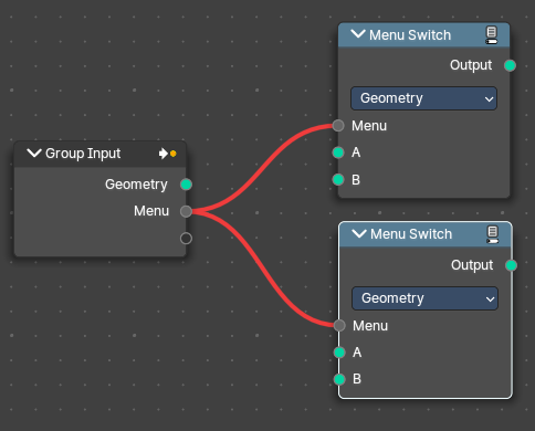
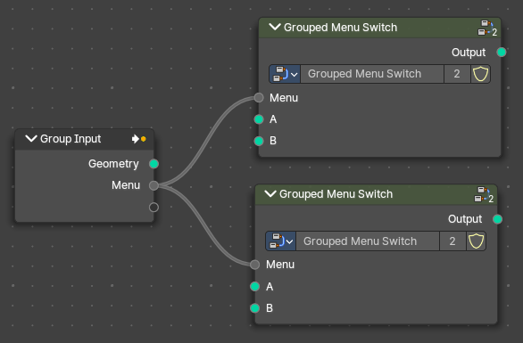
Connecting multiple Menu Switch nodes to the same output creates a conflict. To avoid this, a menu switch can be grouped. Multiple groups of the same type can connect to the same menu.
Note: You cannot plug in the same value socket into the Menu selector. If you’d like to use the same value for various Menu Switches, group the Menu Switch into a Node Group and use the top-level switch override.
Top level grouped Menu Switches with the same inputs work:
Same level Menu Switches with the same input cause a conflict:
Inputs
A / B
Becomes the output if the value is chosen.
Menu
Data type: Menu.
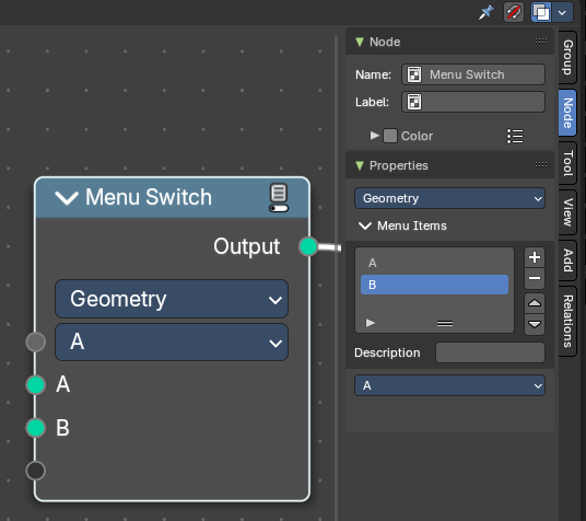
Determines which of the input options will be selected and passed through as the default.
A , B ...
The available input index types that you want to switch between. You can define more input sockets in the sidebar Menu Switch panel.
Note: You can add more menu switch options to the empty socket.
Properties
Data Type
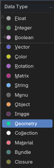
Determines the type of the data that is handled by the node.
Outputs
Output
Data type: Geometry.
The output index.
Random Value
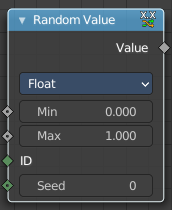
Generates a random value.
Input
Min
Data type: follows the Data Type setting.
The minimum value of the range. This input is only available for Float, Integer, and Vector types.
Max
Data type: follows the Data Type setting.
The maximum value of the range. This input is only available for Float, Integer, and Vector types.
ID
Data type: Integer.
An ID to drive the random number generator seed. By default, this input uses the same value as if the ID Node, which is the id attribute of the context geometry if it exists, and otherwise the index.
Seed
Data type: Integer.
The random seed for the random number generation.
Properties
Data Type
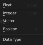
What kind of random value to create. The items should be self explaining.
Output
Value
Data type: follows the Data Type setting.
The output value.
Repeat
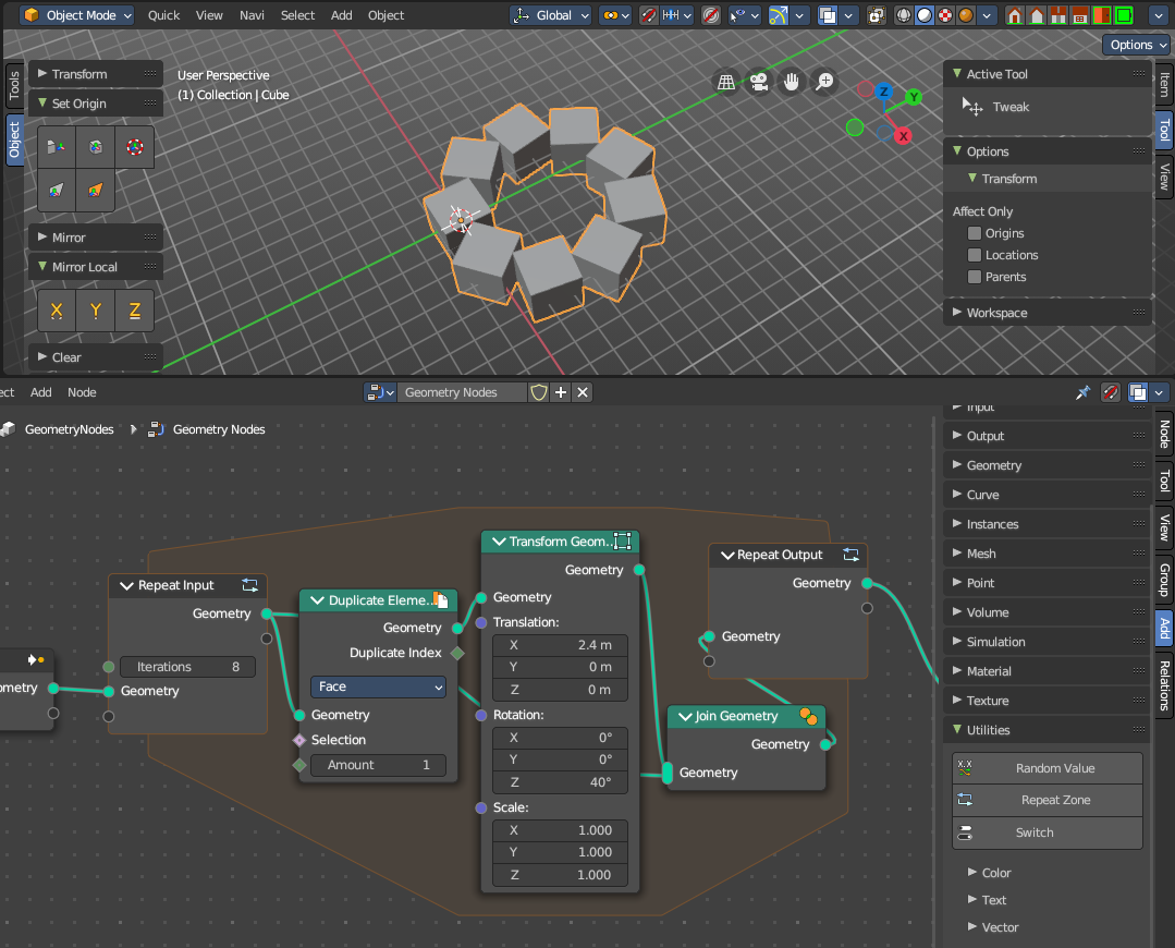
When adding a repeat zone, two nodes are added with a “zone” set between them. The inputs connected to the Repeat Input node reads and gets data at the beginning of the loop before starting the looping - then the data is processed within the zone, here you can set any changes to the data to then repeat the execution again at the beginning of the chain for the next iteration of the loop. This chain of operations is repeated the specified number of times in the Repeat Input node.
In the example in the image above, we duplicate the cube, transform it with a rotation, then join it together again. We do this 8 times in a loop, creating a circular array.
Note: It is not possible to set data outside the Repeat Zone, you can only get data from outside the Repeat Zone. Any data connected from the outside of the zone are constant throughout every iteration based on their value at the current frame. The result of the looping can only be accessed via the Repeat Output node.
Repeat Zone Input
The beginning of the iteration or loop.
Input
Iterations
Number of repetitions or loops.
Geometry
Standard geometry input.
Output
Geometry
Standard geometry output.
Repeat Zone Output
The result and output of the iteration or loop. You can define custom attributes outputs here from the
Inputs
Geometry
Standard geometry output.
Outputs
Geometry
Standard geometry output.
Switch
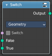
Switch between two inputs values based on a boolean.
Inputs
Switch
Data type: Boolean.
The boolean switch.
A
The input value A. Used when the switch is off.
B
The input value B. Used when the switch is on.
Properties
Input Type
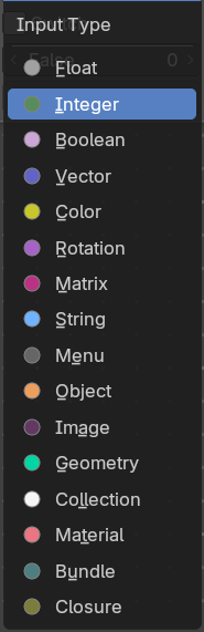
What input type the values are, which defines what type to output then.
Outputs
Output
Data type: Float.
Numerical value output.
Math
Add menu - Utilities - Math
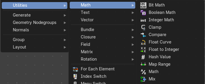
Utility nodes are mainly for mathematical operations.
Bit Math
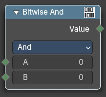
Performs a bit math operation between its inputs.
Inputs
The inputs depends of the chosen method.
Properties
Operation
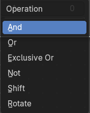
And
Returns a value where the bits of A and B are both set.
Or
Returns a value where the bits of either A or B are set.
Exclusive Or
Returns a value where only one bit of A and B is set.
Not
Returns the opposite bit value of A, in decimal it is equivalent of A = -A -1
Shift
Shifts the bit values of A by the specified Shift amount. Positive values shift left, negative values shift right.
Rotate
Rotates the bit values of A by the specified Shift amount. Positive values rotates left, negative values rotates right.
Output
Boolean
Standard Boolean output.
Boolean Math
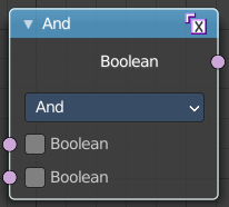
The Boolean Math node performs a basic logical operation between its inputs.
Inputs
Boolean
Data type: Boolean.
Two standard Boolean inputs.
Properties
Operation
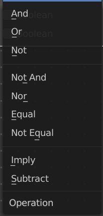
And
True if both inputs are true.
Or
True if either or both inputs are true.
Not
True if both inputs are false.
Not And (NAND)
True when at least one input is false.
Nor (NOR)
True when both inputs are false.
Equal (XNOR)
True when both inputs are equal.
Not Equal (XOR)
True when both inputs are different.
Imply (IMPLY)
True unless the first input is true and the second is false.
Subtract (NIMPLY)
True when the first input is true and the second is false.
Output
Boolean
Data type: Boolean.
Standard Boolean output.
Integer Math
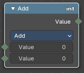
The Boolean Math node provides mathematical operations with integers.
Inputs
Value
Data type: Integer.
Two standard value inputs.
Properties
Functions
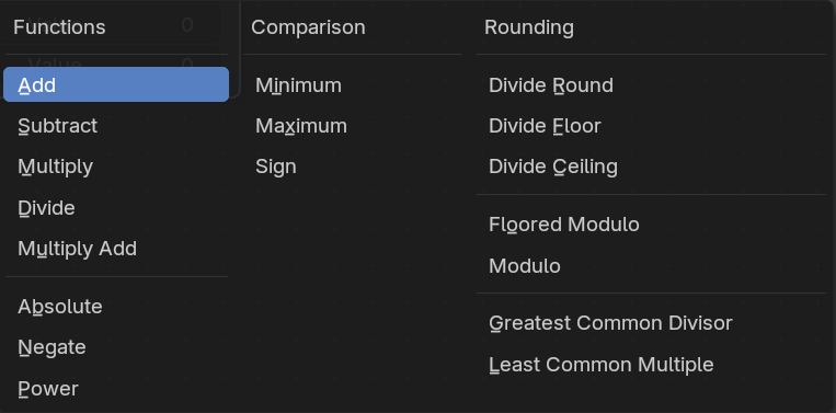
The available mathematical functions to manipulate the input integers.
Output
Value
Data type: Integer.
The value output.
Clamp
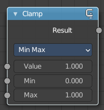
Clamps a value between a minimum and a maximum.
Inputs
Value
Data type: Float.
The input value to be clamped.
Min
Data type: Float.
The minimum value.
Max
Data type: Float.
The maximum value.
Properties
Clamp Type
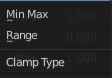
Min Max
Clamp values using Min and Max values.
Range
Clamp values between Min and Max range.
Outputs
Result
Data type: Float.
The input value after clamping.
Compare
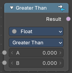
The Compare node takes two inputs and does a math comparison between them.
Inputs
A, B
Standard float value input.
Properties
Input Type
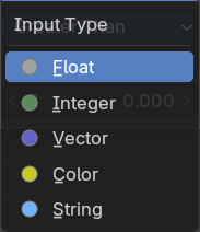
What kind of data to compare.
Besides numbers, vectors, colors and strings, the Compare node can check whether two Objects or two Collections are equal.
Operation
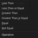
A is less than B
True if A is smaller than B.
A is lesser than or equal B
True if A is smaller or equal than B.
A is greater than B
True if A is bigger than B.
A is greater than or equal B
True if A is bigger or equal than B.
A is equal B
True if A and B are the same.
A is not equal B
True if A and B are different.
Output
Result
Data type: Boolean.
Standard Boolean output.
Float Curve
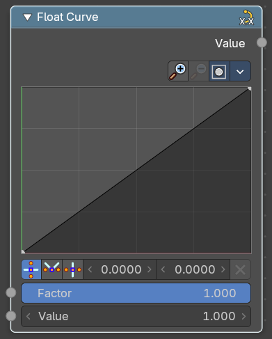
The Float Curve node maps an input float to a curve and outputs a float value. This curve can then be used for profiles for example.
Inputs
Factor
Data type: Float (factor).
How strong the input influences the output value.
Attribute
The input value.
Properties
Curve Field
Channel buttons

Clicking on one of the channels displays the curve for each.
C (Combined RGB), R (Red), G (Green), B (Blue).
Navigation elements
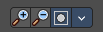
They are described from left to right.
Zoom in and out
The two buttons with the magnifying glass at it zooms in and out in the curve window.
Clipping Options
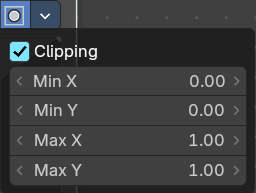
Clipping options. Set up clipping for the stroke.
Tools
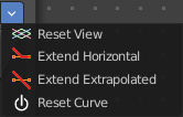
Tools is a menu where you can find some curve related tools.
Reset View
Resets the curve windows zoom.
Extend horizontal
Extends the curve before the first curve point and behind the last curve point horizontally.
Extend extrapolated
Extends the curve before the first curve point and behind the last curve point extrapolated.
Reset Curve
Resets the curve to the initial shape.
Curve edit field
Create and tweak a Bezier curve that varies the input levels (X axis) to produce an output level (Y axis).
Selecting Points
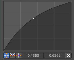
You can select curve points. This reveals two edit boxes for the x and y coordinate of this point.
Selected points can be moved around. Left click at them, hold the mouse button down and move them to a new location.
Adding Points
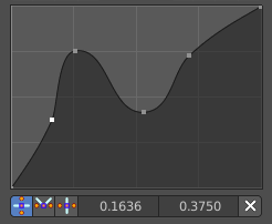
You can add new curve points by simply left clicking at the curve. Move the mouse to position them where you need it.
Curve point settings

When you have a point selected then you will reveal further settings at the bottom.
Vector Handle
Set handle type to Vector.
Auto Handle
Set handle type to Auto.
Auto Clamped Handle
Set handle type to Auto Clamped.
Output
Value
Data type: Float.
The output value.
Float to Integer
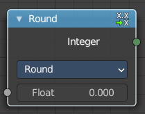
Converts a floating point value into an integer value.
Inputs
Float
Data type: Float.
The input float value.
Properties
Rounding Mode
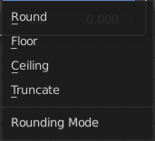
How the float value should be converted.
Outputs
Integer
Data type: Integer.
The output integer value.
Hash Value
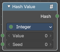
The hash value converts a value input into a hashed value.
Note that Hashes cannot be relied upon to be used as unique identifiers because they are not guaranteed to be unique. It can be used to generate somewhat stable randomness especially in cases where White Noise does not offer enough flexibility.
Input
Value
Data type: follows the Data Type setting.
The input value.
Seed
Data type: follows the Data Type setting.
A seed to randomize the value.
Properties
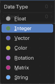
Data Type
What data type to create.
Output
Hash
Data type: follows the Data Type setting.
The hash value output.
Map Range
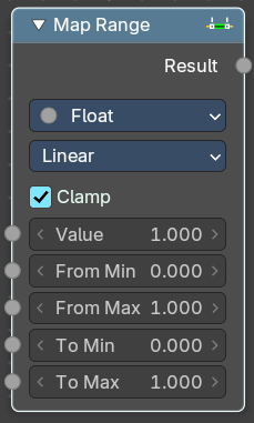
This node converts (maps) an input value range into a destination range. By default, values outside the specified input range will be proportionally mapped as well. This node is similar to Map Value node but provides a more intuitive way to specify the desired output range.
Inputs
Value
Data type: follows the Data Type setting.
Standard value input.
From Min
Data type: follows the Data Type setting.
Start of the input value range.
From Max
Data type: follows the Data Type setting.
End of the input value range.
To Min
Data type: follows the Data Type setting.
Startof the destination range.
To Max
Data type: follows the Data Type setting.
End of the destination range.
Properties
Data Type
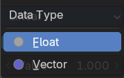
The data type to calculate.
Interpolation Type
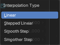
how to interpolate the values between min and max.
Clamp
Clamps values to Min/Max of the destination range.
Outputs
Value
Standard value output.
Math
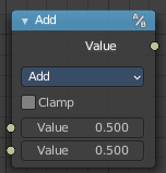
The Math Node performs math operations.
Inputs
The inputs of the node are dynamic. Some inputs are only available with certain operations. For example, the Addend input is only available in the Multiply Add operator.
Value
Data type: Float.
Input Value. Trigonometric functions read this value as radians.
Addend
Input Addend.
Base
Input Base.
Exponent
Input Exponent.
Epsilon
Input Epsilon.
Distance
Input Distance.
Min
Input Minimum.
Max
Input Maximum.
Increment
Input Increment.
Scale
Input Scale.
Degrees
Input Degrees.
Radians
Input Radians.
Properties
Operation
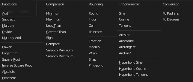
The mathematical operator to be applied to the input values:
Functions
Add
The sum of the two values.
Subtract
The difference between the two values.
Multiply
The product of the two values.
Divide
The division of the first value by the second value.
Multiply Add
The sum of the product of the two values with Addend.
Power
The Base raised to the power of Exponent.
Logarithm
The log of the value with a Base as its base.
Square Root
The square root of the value.
Inverse Square Root
One divided by the square root of the value.
Absolute
The input value is read with without regard to its sign. This turns negative values into positive values.
Exponent
Raises Euler’s number to the power of the value.
Comparison
Minimum
Outputs the smallest of the input values.
Maximum
Outputs the largest of two input values.
Less Than
Outputs 1.0 if the first value is smaller than the second value. Otherwise the output is 0.0.
Greater Than
Outputs 1.0 if the first value is larger than the second value. Otherwise the output is 0.0.
Sign
Extracts the sign of the input value. All positive numbers will output 1.0. All negative numbers will output -1.0. And 0.0 will output 0.0.
Compare
Outputs 1.0 if the difference between the two input values is less than or equal to Epsilon.
Smooth Minimum
Smooth Minimum.
Smooth Maximum
Smooth Maximum.
Rounding
Round
Round the input value to the nearest integer.
Floor
Rounds the input value down to the nearest integer.
Ceil
Rounds the input value up to the nearest integer.
Truncate
Outputs the integer part of the value.
Fraction
Fraction.
Modulo
Outputs the remainder once the first value is divided by the second value.
Wrap
Outputs a value between Min and Max based on the absolute difference between the input value and the nearest integer multiple of Max less than the value.
Snap
Round the input value to down to the nearest integer multiple of Increment.
Ping-pong
The output value is moved between 0.0 and the Scale based on the input value.
Trigonometric
Sine
The Sine of the input value.
Cosine
The Cosine of the input value.
Tangent
The Tangent of the input value.
Arcsine
The Arcsine of the input value.
Arccosine
The Arccosine of the input value.
Arctangent
The Arctangent of the input value.
Arctan2
Outputs the Inverse Tangent of the first value divided by the second value measured in radians.
Hyperbolic Sine
The Hyperbolic Sine of the input value.
Hyperbolic Cosine
The Hyperbolic Cosine of the input value.
Hyperbolic Tangent
The Hyperbolic Tangent of the input value.
Conversion
To Radians
Converts the input from degrees to radians.
To Degrees
Converts the input from radians to degrees.
Clamp
Limits the output to the range (0.0 to 1.0). See Clamp.
Outputs
Value
Data type: Float.
Numerical value output.
Mix
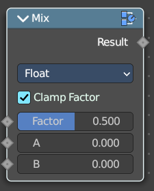
Allows to mix values and vectors in various ways. The node has three different modes. Float, Vector and Color. This node covers the Float mode
Input
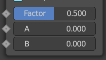
Float
Factor
The mix factor.
A
Float value A input.
B
Float value B input.
Properties
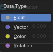
Data Type
The data type to calculate.
Output
Result
Data type: follows the Data Type setting.
The output value or vector.
Text
Add menu - Utilities - Text
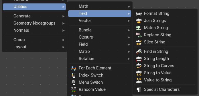
Text object related nodes.
Format String
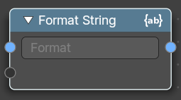
Insert Values into a string using a Python and path template compatible formatting syntax.
The syntax can be found here: https://docs.python.org/3/library/string.html#format-string-syntax
Inputs
Strings
The strings that you want to modify.
Properties
String
The python syntax to modify the string.
Outputs
String
Data type: String.
The output string.
Join Strings
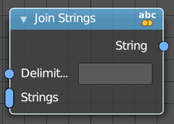
Allows you to join several string into a text string.
Inputs
Delimiter
Data type: String.
Add a delimiter character.
Strings
Data type: String.
The strings that you want to join into one text string.
Outputs
String
Data type: String.
The output string.
Match Strings
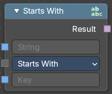
Allows you to compare strings to match conditions
Inputs
String
The input string.
Key
An input key.
Properties
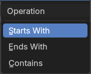
Operation
What string condition to match.
Output
Result
The output strings that matches the condition.
Replace Strings
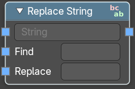
Find and replace strings inside of the input string.
Inputs
String
The input string.
Find
The string part that you want to replace.
Replace
The string part that you use to replace the selected string part.
Outputs
String
The strings that you want to join into one text string.
Slice String
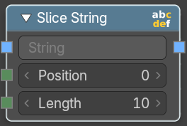
Allows you to extract a string from a substring at given position with given length.
Inputs
String
Data type: String.
The source string.
Position
Data type: Integer.
The start position of the sub string.
Length
Data type: Integer.
The length of the substring.
Outputs
String
Data type: String.
The output substring.
Find in String
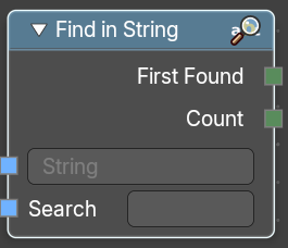
Returns an integer of the total count of matching strings or the first integer position of a matching string
Inputs
String
Data type: String.
The string that you want to search in.
Search
Data type: String.
The string that would be matched in the string search.
Outputs
First Found
Data type: Integer.
Returns the integer position of the first character of the found string.
Count
Data type: Integer.
Returns an integer position of the first character of the found string.
String length
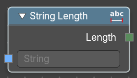
Gives back the number of characters in this string.
Inputs
String
Data type: String.
The string that you want to calculate.
Outputs
Length
Data type: Integer.
How many characters the string has.
String to Curves
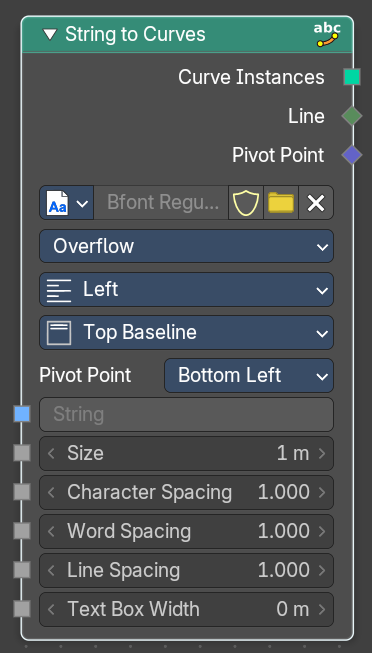
Converts the letters of a text into curve objects.
Inputs
String
Data type: String.
The text string to convert.
Size
Data type: Float (distance).
Size of the string.
Character Spacing
Data type: Float.
The character spacing of the string.
Word Spacing
Data type: Float.
The word spacing of the string.
Line Spacing
Data type: Float.
The line spacing of the string.
Max Width
The maximum width of the string.
Properties
Font property

Font browser
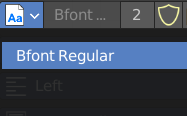
A list of the loaded fonts.
Font Edit Box
The active font.
Number of Users
The number of users for this font.
Fake User
Keep this font in the .blend file even when it has no users. The default font is special in this regards. It will not vanish when you close the file, even when it has no fake user assigned.
Open Font
Load a system font.
Remove
Removes the active font. The default font is special in this regards. You cannot delete it.
Overflow
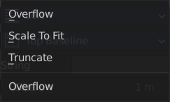
The overflow method for the text.
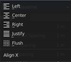
Align X
How to align the text horizontally
Align Y
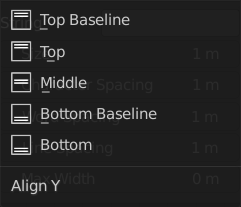
How to align the text vertically.
Pivot Point
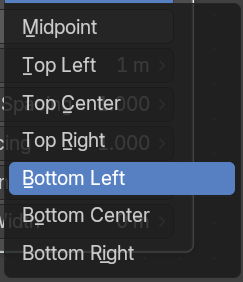
What point of the string to use as the pivot point.
Output
Curve Instances
Data type: Geometry.
The curves output.
Line
Data type: Integer.
Outputs the line number of the character.
Pivot Point
Data type: Vector.
Outputs the selected pivot point position per character.
String to Value
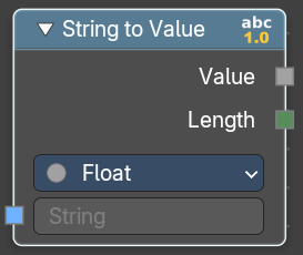
Converts a string input (e.g. "3.14" or "42") into a numeric value that can be used in fields, modifiers, or procedural logic. It also outputs the length of the string for additional control or validation.
Inputs
String
Data type: String.
The input string.
Properties
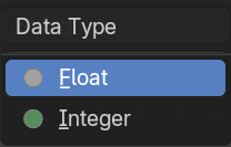
Data Type
Specifies the target data type for conversion
Outputs
Value
The output value.
Length
The number of characters in the input string as an Integer.
Value to String
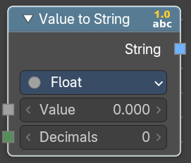
Converts a value to a string.
Inputs
Value
Data type: follows the Data Type setting.
The input value.
Decimals
Data type: Integer.
How many decimals the value has.
Properties
Data Type
Specifies the target data type for conversion
Outputs
String
The output string.
Special Character
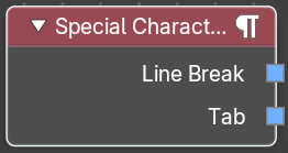
Adds special characters to the text string.
Outputs
Line Break
Adds a Line Break to the text string.
Tab
Adds a tab to the text string.
Vector
Add menu - Vector
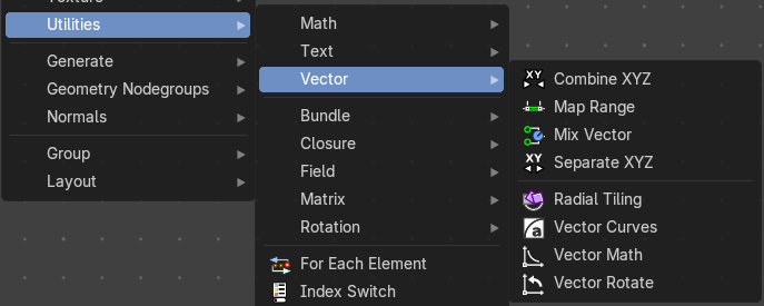
Vector nodes are for calculating vector operations.
Combine XYZ
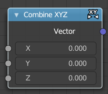
The Combine XYZ Node combines a vector from its individual components.
Inputs
X Y and Z
X, Y and Z values.
Outputs
Color
Color output.
Map Range
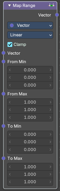
Remap a value from a range to a target range.
Input
From Min
Data type: follows the Data Type setting.
Vector 3 from the minimum input.
From Max
Data type: follows the Data Type setting.
Vector 3 from the maximum input.
To Min
Data type: follows the Data Type setting.
Vector 3 to the minimum input.
To Min
Data type: follows the Data Type setting.
Vector 3 to the maximum input.
Properties
Data Type
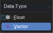
What data to calculate.
Interpolation Type
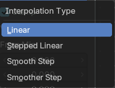
The interpolation method for the operation.
Clamp
Clamp the result to the target range of To Min - To Max.
Outputs
Vector
Data type: Vector.
The output vector.
Mix Vector
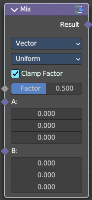
Allows to mix values and vectors in various ways. The node has three different modes. Float, Vector and Color. This here is the node in Vector mode.
Input
Factor
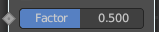
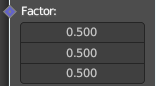
The mix factor. With mode Uniform it is a single value. With mode Non Uniform it is a vector.
A
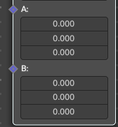
Vector A input.
B
Vector B input.
Properties
Data Type
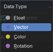
Which mode to use. We cover here the Vector mode.
Factor Mode
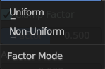
Use a single value or a vector for the factor.
Output
Result
The output value or vector.
Separate XYZ
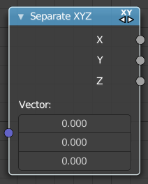
The Separate XYZ Node splits a vector into its individual components.
Inputs
Vector
Data type: Vector.
The Input vector.
Outputs
X, Y and Z
The output vectors for X, Y and Z.
Radial Tiling
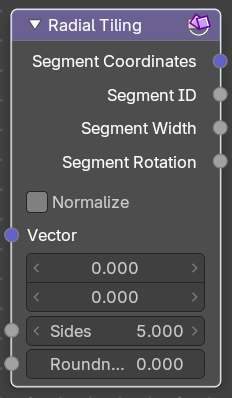
The Separate XYZ Node splits a vector into its individual components.
Inputs
Vector
Data type: Vector (2d).
The Input vector.
Sides
Data type: Float.
Number of angluar segments for tiling.
Roundness
Data type: Float (factor).
Roundness of the segments coordinate systems.
Properties
Normalize
Stretch the textures to fit into each angular segment.
Outputs
Segment Coordinates
Data type: Vector.
The segment coordinates for texture mapping.
Segment ID
Data type: Float.
Unique ID for every segment.
Segment Width
Data type: Float.
The width of every segment.
Segment Rotation
Data type: Float.
The rotation of every segment.
Vector Curves
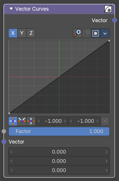
The Vector Curves node maps an input vector components to a curve.
Inputs
Factor
Data type: Float (factor).
Standard vector input.
Vector
Data type: Vector.
Standard vector input.
Properties
Channel
X Y Z

X, Y, Z Channel buttons. Clicking on one of the channels displays the curve for each.
Curve edit field
Create and tweak a Bezier curve that varies the input levels (X axis) to produce an output level (Y axis).
Selecting Points
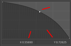
You can select curve points. This reveals two edit boxes for the x and y coordinate of this point.
Selected points can be moved around. Left click at them, hold the mouse button down and move them to a new location.
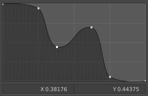
Adding Points
This setting uses the curve widget: click to add points, drag to move them. See Curve Widget in the Interface chapter.
Navigation elements
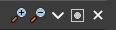
The navigation elements at the top are described from left to right.
Zoom in and out
The two buttons with the magnifying glass at it zooms in and out in the curve window.
Clipping
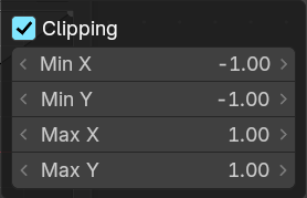
Clipping options. Set up clipping for the stroke.
Tools
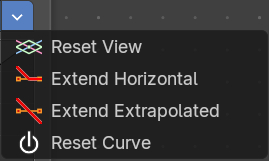
Tools is a menu where you can find some curve related tools.
Reset View
Resets the curve windows zoom.
Extend horizontal
Extends the curve before the first curve point and behind the last curve point horizontally.
Extend extrapolated
Extends the curve before the first curve point and behind the last curve point extrapolated.
Reset Curve
Resets the curve to the initial shape.
Vector Handle

Set handle type to Vector.
Auto Handle
Set handle type to Auto.
Auto Clamped Handle
Set handle type to Auto Clamped.
X Y values
The x and y values of the selected curve point.
Delete Points
Deletes selected curve points.
Outputs
Vector
Data type: Vector.
Standard vector output.
Vector Math
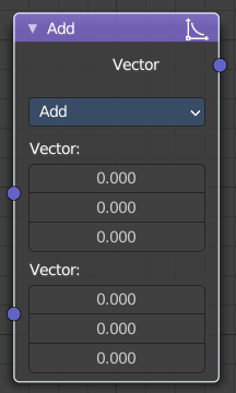
The Vector Math node performs the selected math operation on the input vectors.
Inputs
The inputs of the node are dynamic. Some inputs are only available in certain operations. For instance, the Scale input is only available in the Scale operator.
Vector
Data type: Vector.
Input vector A.
Vector
Data type: Vector.
Input vector B.
Scale
Data type: Float.
Input Scale.
Properties
Operation
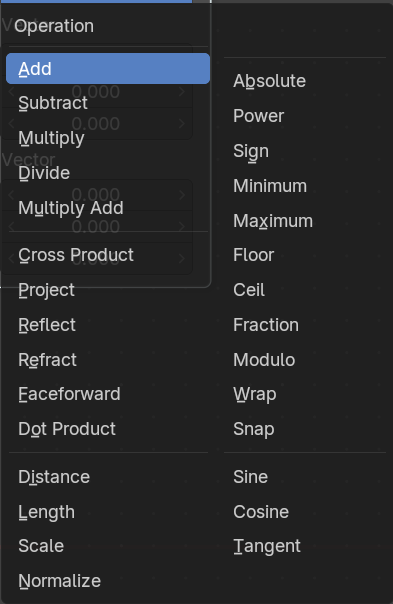
The vector math operator to be applied on the input vectors.
Outputs
The output of the node is dynamic. It is either a vector or a scalar depending on the operator. For instance, the Length operator have a scalar output while the Add operator have a vector output.
Vector
Data type: Vector.
Output vector.
Value
Data type: Float.
Output value.
Vector Rotate
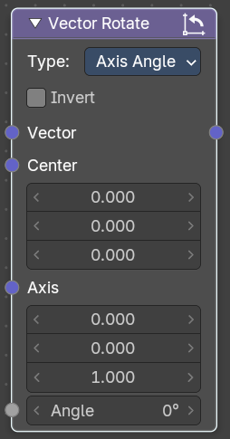
The Vector Rotate node allows rotations by a vector.
Inputs
The inputs of the node are dynamic. Some inputs are only available in certain operations. For instance, the Angle input is just available with the Axis Angle type.
Vector
Data type: Vector.
Input vector.
Center
Data type: Vector.
Input Center
Axis
Data type: Vector.
Input Axis.
Angle
Data type: Float (angle).
Input Angle
Properties
Type
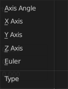
The rotation type.
Outputs
Vector
Data type: Vector.
The Output vector.
Bundle
Add menu - Bundle
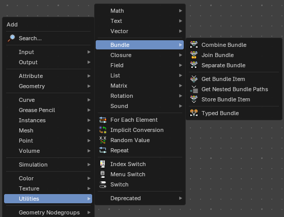
Bundles are like packed containers—they let you group multiple values (like vectors, floats, booleans) into a single wire. Think of them as a way to package data together and pass it around cleanly.
Combine Bundle
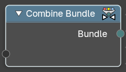
This node takes multiple inputs and wraps them into a single bundle.
Inputs
Sockets
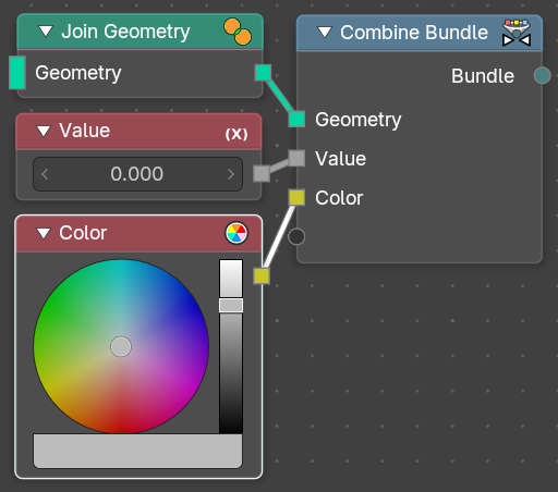
This is a dynamic socket that will populate with whatever you want to plug into it for later use. Accepts one or more bundle-compatible data streams.
These could represent attributes, geometry sets, vales, vectors, or grouped attributes depending on context.
Outputs
Bundle Socket
Standard bundle socket with a unified bundle containing all input elements. Use this to pass the packaged sockets to a Separate Bundle node for later user down the node tree lines.
Separate Bundle
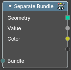
This node unpacks a bundle back into its individual components.
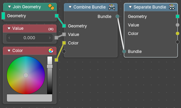
Inputs
The inputs of the node are dynamic. Some inputs are only available in certain operations. For instance, the Scale input is only available in the Scale operator.
Bundle
Data type: Bundle.
Standard bundle socket with a unified bundle containing all input elements from a Combine Bundle node.
Outputs
Sockets
This is a dynamic series of socket that will populate with whatever is available from the incoming bundle line. Ouptuts one or more bundle-compatible data streams. These could represent attributes, geometry sets, vales, vectors, or grouped attributes depending on context.
Join Bundle
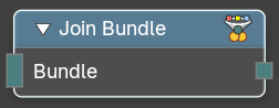
Merges two or more Bundle inputs into a single output bundle.
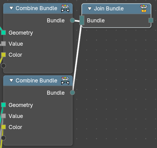
This enables modular data structuring, reuse, and override logic in procedural workflows—similar to combining structs in programming.
Inputs
Bundle
Data type: Bundle.
Bundle 1, Bundle 2, … Accepts multiple bundles created via the Combine Bundle node. Each bundle may contain different types of data (e.g. Float, Vector, String, Color)
Outputs
Bundle Socket
Standard bundle socket with a unified bundle containing all input elements. Use this to pass the packaged sockets to a Separate Bundle node for later user down the node tree lines.
Get Nested Bundle Paths
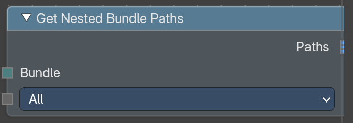
Lists where things are stored inside a bundle that has other bundles in it. Each path is a string, with the names of the nested bundles and the item joined by /. Use it to find items without knowing their names in advance.
A nested bundle that has a Type item is handled as one item. The node does not look inside it.
Inputs
Bundle
The bundle to search.
Mode
Chooses which paths are listed.
All lists the path of every item.
Bundle Type lists the paths of nested bundles whose Type matches the Bundle Type input.
Data Type lists the paths of items that have the chosen Data Type.
Pattern Mode
Only used in Bundle Type mode. Chooses how the Bundle Type input is compared with the Type of each nested bundle.
Exact matches only the same text.
Wildcard allows one * in the text, which stands for any characters. If you use more than one *, the node shows an error.
Bundle Type
Only used in Bundle Type mode. The type to look for. If it is empty, no paths are listed.
Data Type
Only used in Data Type mode. Items with this data type are listed.
Outputs
Paths
A list of strings, one path per item found, sorted alphabetically. If no bundle is connected, the list is empty.
Get Geometry Bundle
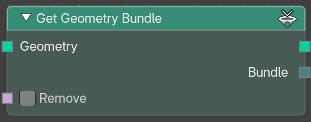
Gets the bundle that is stored on a geometry. Use it to read data that was attached to a geometry with Set Geometry Bundle.
Inputs
Geometry
The geometry to get the bundle from.
Remove
Off by default. When on, the bundle is taken off the geometry that comes out of the node. This can avoid unneeded copies of data.
Outputs
Geometry
The input geometry. It no longer holds the bundle when Remove is on.
Bundle
The bundle that was stored on the geometry.
Typed Bundle
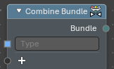
Adds a Combine Bundle node that already has a String item named Type. The Type tells other nodes what kind of bundle this is, for example when you look for bundles with Get Nested Bundle Paths.
Click the Type field of the new node and pick a type from the list, or type your own name. When you pick a known type, the node adds the items that type needs.
Closure
Add menu - Closure
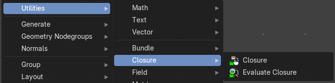
Vector nodes are for calculating vector operations.
Closures allow you to pass custom logic into node groups—like injecting a mini-function or behavior block. They’re ideal for creating reusable, pluggable systems where the user can define part of the logic externally.
Closure Zone
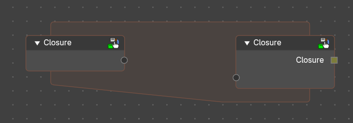
The closure function to be executed.
Purpose
Defines logic that will be injected into a node group or node tree. Think of it as a sandbox where the user builds a mini-node tree that gets executed when the closure is evaluated during the execution of another node tree.
A Closure encapsulates the logic defined in the Closure Zone. This output is typically connected to an Evaluate Closure node inside a node group or injected into another node tree.
Use Cases:
- Custom deformation logic injected into a reusable node group.
- Procedural scattering patterns defined externally.
- Field-based attribute manipulation with user-defined formulas.
- Behavior overrides for geometry processing pipelines.
Behavior
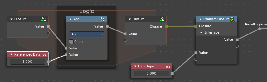
The Closure Node creates a Closure Zone—a subgraph where the logic is built using the declared inputs. This zone behaves like a function.
- Closure Inputs appear as sockets at the top of the zone. Data from outside the zone can also be referenced.
- Outputs are defined using Closure output nodes.
<!-- -->
- The logic inside is encapsulated and only runs when evaluated externally.
How It Works (Conceptually)
- Authoring: You define a Closure Zone with custom logic (e.g., a tree scattering pattern).
- Packaging: The Closure node wraps that logic into a closure line.
- Injection: Inside a node group or elsewhere in a node tree, the Evaluate Closure node pulls in that logic and runs it with the provided inputs.
- Modularity: You can swap closures to change behavior without modifying the node tree or nodegroup itself.
When the node group containing an Evaluate Closure node runs, it pulls in the logic from the Closure Zone and executes it in place. The zone is not executed immediately—it’s stored as a callable block.
Requirements
Input and output names in the Closure Zone must match those expected by the Evaluate Closure node.
Can include any Geometry Nodes logic, including fields, math, distribution patterns, etc.
Properties
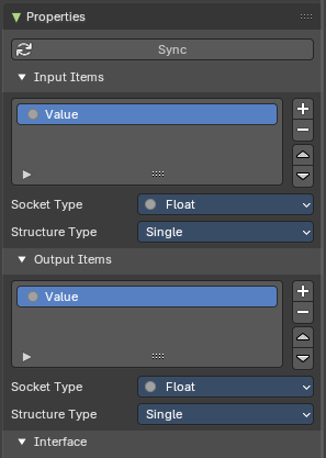
These panel defines the parameters that the closure will pass when evaluated. Each item becomes a socket in the Closure Zone.
You can access these properties in the sidebar to the right in the Node tab.
Sync Button
Updates the sockets to what is actually used from a Closure Zone, meaning the input/output sockets update to what is evaluated in the logic of the closure automatically. Useful to not do this manually.
Input Items
Parametersofvalues passed into the Closure logic (e.g., geometry, fields, values) for user customizability.
Output Items
Whatever parameters the Closure logic returns—could be geometry, fields, instances, values, etc
Common Properties
Add / Remove / Reorder Controls
+ (Add): Creates a new input socket. – (Remove): Deletes the selected input. ↑ / ↓ (Reorder): Adjusts the order of inputs for visual clarity and UX consistency.
Name
Identifier for the input. Must match the name used in Evaluate Closure.
Socket Type
Data type of the input (e.g., Float, Vector, Boolean, Geometry, Field).
Structure Type
Defines how the input is treated: Auto, Dynamic, Field, Grid, List, or Single.
Evaluate Closure
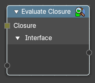
This node calls the logic stored in the Closure object.
It passes in the provided parameters and returns the result of the closure’s internal node tree. Execution is deferred—the logic only runs when this node is evaluated in the context of the node group.
Closure Input
A Closure socket input created by a Closure zone. This contains the logic to be executed from that Closure zone.
Interface Inputs / Outputs
Named inputs/outputs from the Closure properties that match the Closure Zone’s expected parameters for the enclosed logic to be evaluated.
Properties
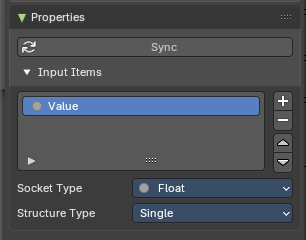
This panel defines the parameters that the closure will accept when evaluated. Each item becomes a socket in the Closure Zone.
You can access these properties in the sidebar to the right in the Node tab.
Sync Button
Updates the sockets to what is actually used from a Closure Zone, meaning the input/output sockets update to what is evaluated in the logic of the closure automatically. Useful to not do this manually.
Add / Remove / Reorder Controls
+ (Add)
Creates a new input socket. – (Remove): Deletes the selected input. ↑ / ↓ (Reorder): Adjusts the order of inputs for visual clarity and UX consistency.
Name
Identifier for the input. Must match the name used in Evaluate Closure.
Socket Type
Data type of the input (e.g., Float, Vector, Boolean, Geometry, Field).
Structure Type
Defines how the input is treated: Auto, Dynamic, Field, Grid, List, or Single.
Field
Add menu - Utilities - Field
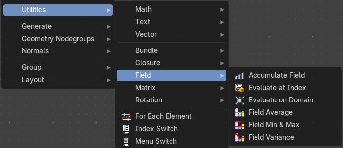
Field nodes.
Accumulate Field
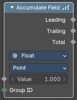
Creates a running total of a given Vector, Float, or Int field.
Inputs
Value
Data type: follows the Data Type setting.
The field to be accumulated.
Group Index
The values of this input are used to aggregate the input into separate 'bins', creating multiple accumulations.
Properties
Data Type
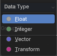
What data type to work with.
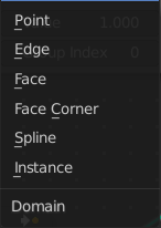
Domain
From which domain to use the data.
Outputs
Leading and Trailing
Returns the running totals starting at either the first value of each accumulations or 0 if there is no data
Total
Data type: follows the Data Type setting.
Returns the total accumulation at all positions of the field.
Cluster by Distance
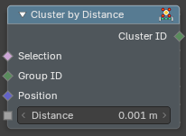
Sorts elements into groups by how close together they are. Every group gets a number, the Cluster ID, and all elements in one group share it. Use it to find points that belong to the same blob, to give each pile of scattered points its own random color, or to feed Merge Points so that near points are merged into one. Elements within the Distance of each other end up in the same cluster, and a cluster can grow as a chain from one element to the next.
Inputs
Selection
Data type: Boolean.
Which elements are put into clusters.
Group ID
Data type: Integer.
Elements only join a cluster with others that have the same Group ID. Use it to keep different kinds of elements apart, for example points of different layers.
Position
Data type: Vector.
The position used to measure the distance. It is usually the Position node, but you can use any vector.
Distance
Data type: Float (distance).
Elements closer than this value belong to the same cluster.
Outputs
Cluster ID
Data type: Integer.
The number of the cluster. The number is the index of the first element of the cluster, so the first element of a cluster has its own index as ID.
How to use
Take five points at x = 0, 0.0005, 0.002, 1 and 1.0005, and set Distance to 0.001. The Cluster ID is 0, 0, 2, 3, 3. The first two points are close enough to share a cluster, the third is too far away and is alone, and the last two form a second cluster. Store the Cluster ID with Store Named Attribute to look at it in the spreadsheet.
Evaluate at Index
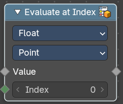
This node allows accessing data of other elements in the context geometry.
It is similar to the Transfer Attribute node in Index mode. The main difference
is that this node does not require a geometry input, because the context
is used.
Inputs
Index
Data type: Integer.
Input Index.
Value
Data type: follows the Data Type setting.
Input Value.
Properties
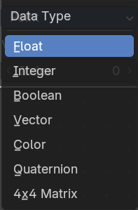
Data Type
What data type to calculate.
Domain
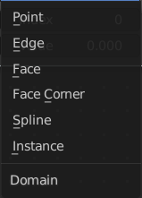
What geometry to calculate.
Output
Value
Data type: follows the Data Type setting.
The output value.
Evaluate on Domain
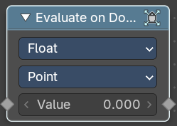
This node evaluates an existing field on a separate domain in a larger field context - an alternative to the Capture Attribute node. This nodes gets the field type of an existing field from the input socket and interpolates the field type as an array in the output socket.
Inputs
Value
Data type: follows the Data Type setting.
The input value to get the field.
Properties
Data Type
Select the Data Type - which can be float, integer, vector, color and boolean.
Domain
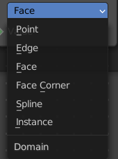
The domain the Field evaluates. This gets and filters the field type. The domain can be point, edge, face, face corner, spline or instance.
Outputs
Value
Data type: follows the Data Type setting.
The output value.
Field Average
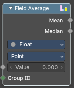
Calculate the mean and median of a given field.
Inputs
Value
Data type: follows the Data Type setting.
The input value to get the field.
Group ID
Data type: Integer.
The input Group ID to get the field.
Properties
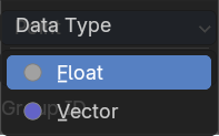
Data Type
Select the Data Type - which can be float, integer, vector, color and boolean.
Domain
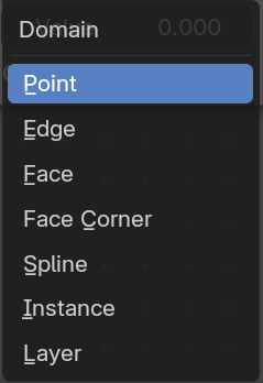
The domain the Field evaluates. This gets and filters the field type. The domain can be point, edge, face, face corner, spline or instance.
Outputs
Mean
Data type: follows the Data Type setting.
The Mean output value.
Median
Data type: follows the Data Type setting.
The Median output value.
Field Min & Max
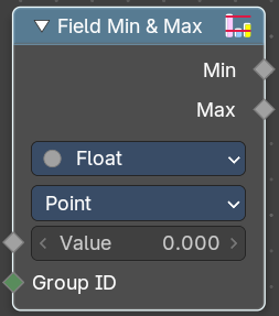
Calculate the minimum and maximum of a given field.
Inputs
Value
Data type: follows the Data Type setting.
The input value to get the field.
Group ID
Data type: Integer.
The input Group ID to get the field.
Properties
Data Type
Select the Data Type - which can be float, integer, vector, color and boolean.
Domain
The domain the Field evaluates. This gets and filters the field type. The domain can be point, edge, face, face corner, spline or instance.
Outputs
Min
Data type: follows the Data Type setting.
The Min output value.
Max
Data type: follows the Data Type setting.
The Max output value.
Field Variance
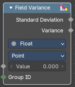
Calculate the standard derivation and variance of a given field.
Inputs
Value
Data type: follows the Data Type setting.
The input value to get the field.
Group ID
Data type: Integer.
The input Group ID to get the field.
Properties
Data Type
Select the Data Type - which can be float, integer, vector, color and boolean.
Domain
The domain the Field evaluates. This gets and filters the field type. The domain can be point, edge, face, face corner, spline or instance.
Outputs
Standard derivation
The Min output value.
Variance
Data type: follows the Data Type setting.
The Max output value.
Matrix
Add menu - Utilities - Matrix
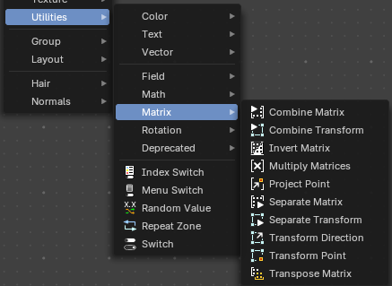
Matrix nodes.
Combine Matrix
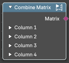
Combines values into a matrix. A matrix is something like a transform cage. A vector 4 in 4 dimensions.
Inputs
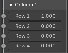
Column 1 , 2, 3, 4
Allows you to combine values into the matrix. A matrix is made of four vector 4 in 4 dimensions. So 16 values.
Output
Matrix
Data type: Matrix.
The output matrix.
Combine Transform
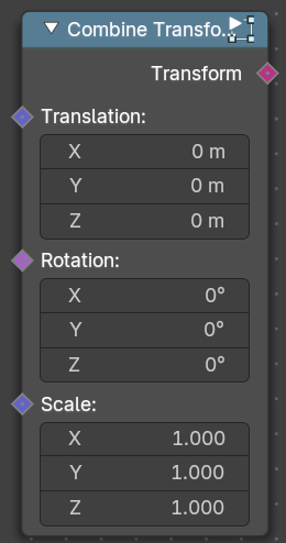
Combines transforms.
Inputs
Translation
Data type: Vector (translation).
The translation input vector.
Rotation
Data type: Rotation.
The rotation input vector.
Scale
Data type: Vector (XYZ).
The scale input vector.
Outputs
Transform
Data type: Matrix.
The output transform.
Matrix Determinant
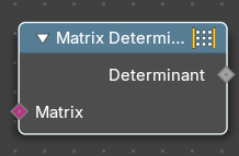
The Matrix Determinant Node is used for calculating the determinant of a given matrix. Use this node to evaluate whether a matrix has properties for invertibility, scaling, and orientation.
Inputs
Matgrix
Accepts a matrix input.
Outputs
Determinant
Data type: Float.
Returns a single numerical value representing the determinant of the input matrix. If the determinant is zero, the matrix is non-invertible.
Invert Matrix
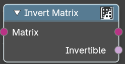
Inverts the matrix values.
Inputs
Matrix
Data type: Matrix.
The input matrix.
Outputs
Matrix
Data type: Matrix.
The output matrix.
Invertible
Data type: Boolean.
The inverted values.
Multiply Matrix
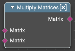
Multiplies the values of two matrices.
Inputs
Matrix, Matrix
The input matrices
Outputs
Matrix
The output matrix.
Project Point
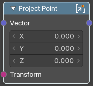
Projects a transform point by a vector.
Inputs
Vector
Data type: Vector (XYZ).
The input vector
Transform
Data type: Matrix.
The input transform point
Outputs
Vector
Data type: Vector (XYZ).
The output vector.
Separate Matrix
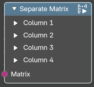
Extract single values from a matrix. A matrix is something like a transform cage. A vector 4 in 4 dimensions.
Inputs
Matrix
Data type: Matrix.
The input matrix.
Output
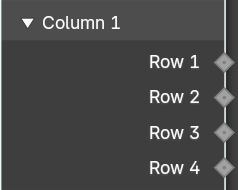
Column 1 , 2, 3, 4
Extract the values from a row in a column. A matrix is made of four vector 4 in 4 dimensions. So 16 values.
Separate Transform
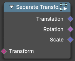
Extracts the translation, rotation or scale values from a transform.
Inputs
Transform
Data type: Matrix.
The input transform.
Outputs
Translation
Data type: Vector (translation).
The translation output vector.
Rotation
Data type: Rotation.
The rotation output vector.
Scale
Data type: Vector (XYZ).
The scale output vector.
Transform Direction
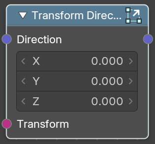
Set the direction of a transform.
Inputs
Direction
Data type: Vector (XYZ).
The input vector 3.
Transform
Data type: Matrix.
The input transform.
Outputs
Direction
Data type: Vector (XYZ).
The output direction.
Transform Point
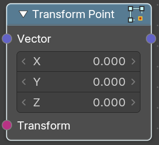
Transform a transform point.
Inputs
Vector
Data type: Vector (XYZ).
The input vector 3.
Transform
Data type: Matrix.
The input transform.
Outputs
Direction
The output vector.
Transpose Matrix
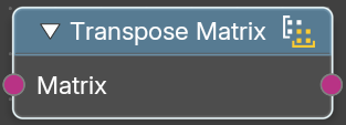
Retreive the transpose matrix from a matrix.
Inputs
Matrix
Data type: Matrix.
The input matrix.
Outputs
Matrix
Data type: Matrix.
The output transpose matrix.
Rotation
Add menu - Utilities - Rotation
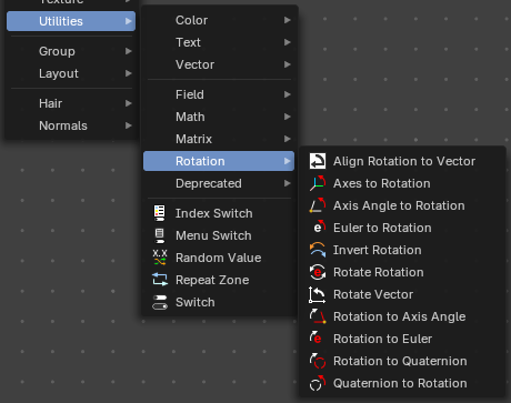
Utility nodes are mainly for mathematical operations.
Align Rotation to Vector
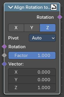
Aligns a rotation to a vector.
Inputs
Rotation
Data type: Rotation.
The input euler rotation vector.
Factor
Data type: Float (factor).
The factor to align the euler value to the vector.
Vector
Data type: Vector (XYZ).
The vector to align to.
Properties
Align Axis
To which axis to align the vector.
Pivot
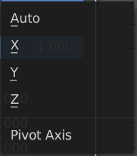
The pivot axis.
Output
Rotation
Data type: Rotation.
The output rotation euler angle.
Axes to rotation
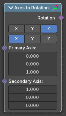
Creates a rotation from a primary and a secondary axis. The axis should be ideally orthogonal.
Inputs
Primary Axis
Data type: Vector.
The axis to rotate around.
Secondary Axis
Data type: Vector.
The secondary axis that gives the alignment.
Properties
Primary axis
Which axis to rotate around.
Secondary Axis
Which axis to align to.
Outputs
Rotation
Data type: Rotation.
The output rotation euler angle.
Axis Angle to Rotation
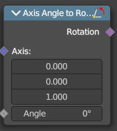
Converts an axis angle to a rotation.
Inputs
Axis
Data type: Vector.
The input axis.
Angle
Data type: Float (angle).
The input angle.
Outputs
Rotation
Data type: Rotation.
The output rotation value.
Euler to Rotation
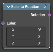
Converts an euler angle to a rotation.
Inputs
Euler
Data type: Vector (euler).
The input euler angle vector.
Outputs
Rotation
Data type: Rotation.
The output rotation value.
Invert Rotation
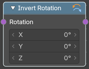
Inverts a rotation
Inputs
Rotation
Data type: Rotation.
The input rotation vector.
Outputs
Rotation
Data type: Rotation.
The output rotation value.
Mix Rotation
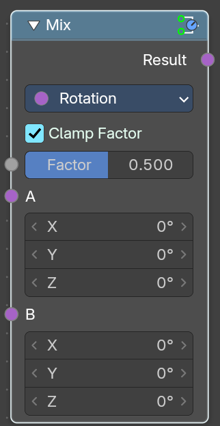
Rotates an euler rotation by another euler rotation.
Inputs
Factor
amount of mixing between a and b inputs.
A, B
The input.
Properties
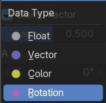
Data Type
What data to calculate.
Outputs
Rotation
The euler angle output.
Rotate Rotation
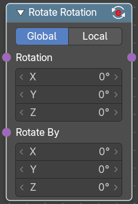
Rotates an euler rotation by another euler rotation.
Inputs
Rotation
Data type: Rotation.
Use the rotation of an existing geometry.
Rotate By
Data type: Rotation.
The input rotation.
Properties
Rotate Space
Global
Rotate by the global orientation
Local
Rotate by the local orientation
Outputs
Rotation
Data type: Rotation.
The euler angle output.
Rotate Vector
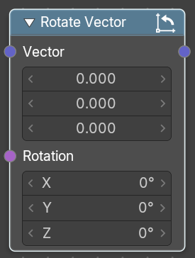
Rotates a vector.
Inputs
Vector
Data type: Vector.
The input vector.
Rotation
Data type: Rotation.
The input rotation.
Outputs
Rotation
The output rotation value.
Rotation to Axis Angle
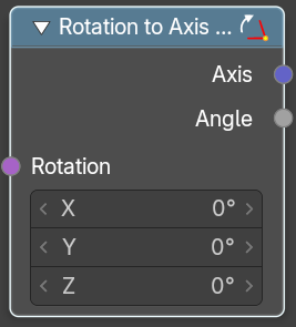
Converts a rotation vector to axis angle.
Inputs
Rotation
Data type: Rotation.
The input vector.
Outputs
Axis
Data type: Vector.
The axis output.
Angle
Data type: Float (angle).
The angle output.
Rotation Euler
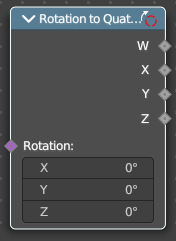
Converts a rotation vector to an euler angle.
Inputs
Rotation
The input vector.
Outputs
Euler
The euler angle.
Rotation to Quaternion
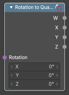
Converts a quaternion to a rotation vector.
Inputs
Rotation
Data type: Rotation.
The input vector.
Outputs
W, X, Y, Z
The single output values of the quaternion.
Quaternion to Rotation
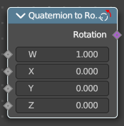
Converts a rotation vector to a quaternion.
Inputs
W, X, Y, Z
The single input values of the quaternion.
Outputs
Rotation
Data type: Rotation.
The output rotation.
Deprecated
Add menu - Deprecated
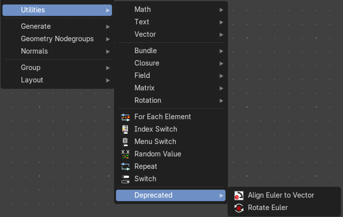
These deprecated nodes are kept for compatibility reasons.
Align Euler to Vector (Deprecated)
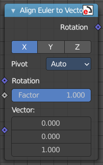
Aligns a euler value to a vector.
Inputs
Rotation
The input euler rotation vector.
Factor
The factor to align the euler value to the vector.
Vector
The vector to align to.
Properties
Align Axis
To which axis to align the vector.
Pivot
The pivot axis.
Output
Rotation
The output rotation euler angle.
Rotate Euler (Deprecated)
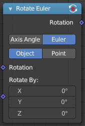
Rotates an euler rotation. This node will be removed in the near future. Alternatively use the Rotate Rotation node.
Inputs
Rotation
Use the rotation of an existing geometry.
Rotate By
The input rotation.
Properties
Rotate Type
Axis Angle
Rotate around an axis by an angle.
Euler
Rotate around the x, y and z axis.
Rotate Space
Object
Rotate points in the local space of the object.
Point
Rotate every point in its local space.
Outputs
Rotation
The euler angle output.