








































Header
The text menus are covered in an individual chapter each.
- Add Menu — Every node you can add, by category: open a category for its nodes.
Tools and Options
Introduction
This chapter here is about the tools, modes and options elements in the header of the geometry nodes editor.
The text menus are covered in an individual chapter each. They vary too much, dependent of mode and object type.
Header Tabs

The tabs at the very left allows you to switch between the most important node editor types by one click. Compositor Editor, Geometry Nodes Editor and Shader Editor.
Geometry Nodes Type
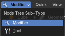
This drop down is to change the Geometry Nodes Type, which are contextual modes that you can choose to create a node-group-defined tool that will later show in the interface as act once operators or as procedural modifiers.
Any geometry node group can then be stored as assets, linked and/or appended to other files.
Example: You can create a node tree in the Tools mode of the Geometry Nodes editor that randomly extrudes then deletes faces, then use that as an Act Once operator on your meshes to model destructively in a linear workflow.
| Entry | What it does |
|---|---|
| Modifier | The context mode to create procedural modifier stack tool. |
| Tool | The context mode to create act once operator tools. In this mode some exclusive nodes are displayed in the Add header menu and Add sidebar. |
Use
Creating a Tool
Switch the Geometry Nodes Type to Tool, then create a new Node Group Tool. Create your operation using Geometry Nodes.
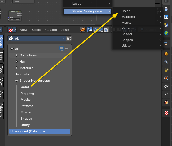
When ready, define the Mode and Data-Type, Asset status, and Catalog assigned to this Node Group Tool, then the Node Group will now become an act-once operator accessible from in the interface.
Note: New node groups created in the tool context will be enabled as Tool in the sidebar by default, though to share them in other files you may need to link, append or mark as asset with the Asset Browser for later use.
Defining as an Asset
To share a node group as a tool in other *.blend files, you need to store the node group as an asset for the Asset Browser. The asset catalog you assign the asset to will be used to determine where the tool will go in the designated menus.
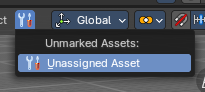
To define where the Node Group Tool is located in the interface, you need to assign the asset to a catalogue in the Asset Browser Editor. If the catalog name matches an existing menu in the interface, the tool will be appended to that specific menu. Assets that have no catalog assigned to them, or local tools, are exposed in the “Unassigned (Catalogue)” menu.
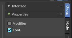
Note: To define if a node group is exposed in the Modifier add menu or into the Tool add menus, go to the sidebar to define it.
Modifier
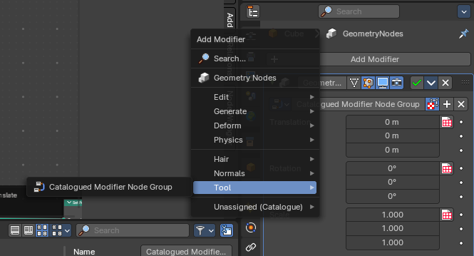
When assigning as a Modifier, the nodegroup asset will show up in the Add menu of the Modifier Stack in the Properties Editor under the assigned asset catalogue name.
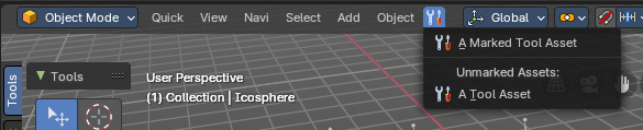
Example: In the image to the right, the marked nodegroup has the catalogue “Tool” assigned. You can also see the “Essentials” node groups also designated as modifier nodegroups.
Tool
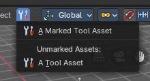
When assigning as a Tool, the geometry nodes tool nodegroup will show up in the 3D View Editor in the header under the assigned Asset catalogue name – otherwise it will be assigned to the Unassigned (Catalogue) header menu.
Note: You can have both a geometry nodes tool and modifier stack nodegroup simultaneously.
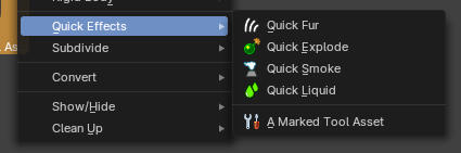
Example: In the image to the right, the marked nodegroup has the catalogue “Object” and a sub catalogue “Quick Effects” assigned. It now is located in the existing in the header.
Unassigned (Catalogue)
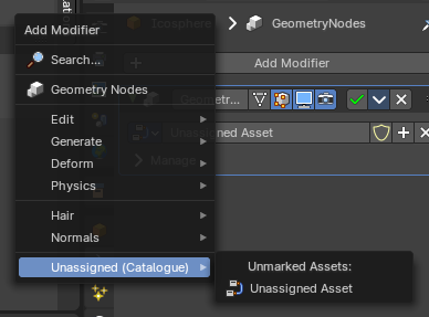
When a nodegroupd stored as a Modifier or Tool without a catalogue, it will be exposed in the submenu called “Unassigned (Catalogue)”. Both marked and unmarked nodegroups will display here if there is not catalogue assigned from the Asset Browser.
Defining Modes and Data-Types
Node group tools must specify which modes and object types they support to determine where the tool is exposed in the user interface.
Types
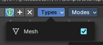
The type of object where the tool is contextually accessible.
Modes
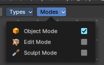
The mode where the tool is contextually accessible.
Tool-specific Nodes
The following nodes are only supported in the Tool context:
- Add>Input>Scene>3D Cursor Node
<!-- -->
- Add>Mesh>Read>Face Set Node
- Add>Geometry>Read>Selection Node
- Add>Mesh>Read>Set Face Set Node
- Add>Geometry>Write>Set Selection Node
Note: The Self Object node returns the Active object when inside a Tool node group.
Geometry Nodes Prop

Manage the nodes. If there is no geometry node tree for the current object, then you will see the New button

Data Browser
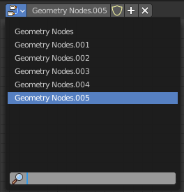
The list of available geometry node trees in the scene.
Edit box
The name of the current active geometry node tree. Here you can also rename the node tree.
Add Fake User
Wit this button you assign a fake user to this selected geometry node tree.
Data, like node trees, that is not longer linked to anything else gets removed when you save and reload a scene. Bforartists has the concept of fake users to go around this behavior. An image with a fake user is in fact linked to something. And so it is not lost when you save and reload the scene.
| Entry | What it does |
|---|---|
| Fake User | The number of users that uses this data. Data with a user number of 0 will be removed with closing Bforartists. |
| Duplicate | Duplicates the current node group. |
| Remove | Removes the geometry node tree. To delete it completely you need to purge it. See Fake user. |
Options

At the right side you will see some options.
| Entry | What it does |
|---|---|
| Pin (pin icon) | The pin button will keep the current node tree selection fixed. When a node tree is pinned, it will remain visible in the shader editor even when another object is selected. |
| Snap | Activates snapping. The snapping happens relative to the groundgrid. |
Geometry node Overlays
Show Overlays
Show or hide the overlays.
Node Editor Overlays
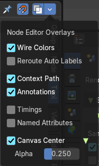
Activates the node editor overlays. When the tool is activated, then you will also overlays settings in the editor. The drop down arrow to the right shows different overlay types.
Wire Colors
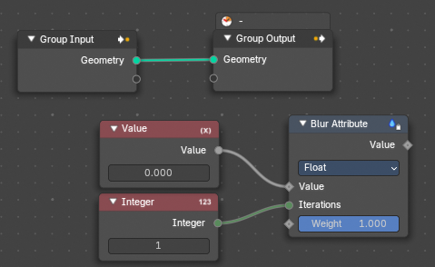
Color node links based on their connected sockets.
Example: The Geometry socket is green that makes a green line, and the Integer socket is dark green that makes a dark green line.
Reroute Auto Labels
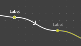
Label reroute nodes based on the label of connected reroute nodes.
Example: The first reroute label to the right has concurring reroute labels down the line. If you toggle this off, the concurring reroute labels down the line won’t contain labels.
Context Path

Display breadcrumbs for the editor’s context.
Annotations
Shows annotations for this editor view that have been drawn by the annotation tool.
Timings
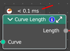
Shows a timing box above each node to indicate the evaluation time of it.. This option is only available for compositing and geometry nodes.
Named Attributes
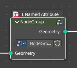
Adds an overlay that helps users to see where named attributes are used with node groups
This helps to see where named attributes are used.
Canvas Center
Show the canvas center and its lines.
Alpha
The transparency of the red and green center line.
Quick Menu
Quick Menu
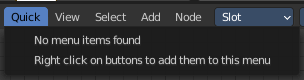
The quick menu, or in long Quick Favorites menu, is a menu that can be customized to your needs. Here you can add operators for quick access.
It is located in the header. But it can be called by hotkey Q directly under the mouse. This hotkey works in other editors too.
When the menu is empty, then you will see the message "No Menu Items found". This means that you first have to add some tools to the menu. It is a user configurable menu.
Note that added operators in this menu does not have icons. Just text.
Adding an operator to the Quick menu
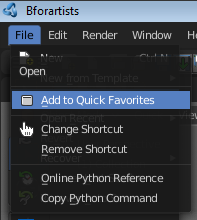
Open the panel or the menu where your operator is that you want to add.
Let's add the open command from the File menu. Open the File menu, right click at open, and choose Add to Quick Favorites.
Do the same with Save As. We should now have two new menu items in the Quick menu, which you can use now.
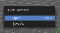
As a rule of thumb, when the right click menu has an Add to Quick Favorites, then you can add it to the quick menu.
Note that you can also add operators from the tool shelf at the left. And also operators from other editor types. Some other editors have their own quick menu though. The Image Editor for example. These operators gets added in the quick menu of the image editor then. And does not show in the quick menu in the header of the 3D view.
Adding a menu to the Quick menu
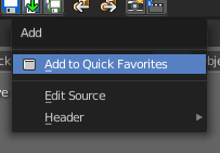
It is also possible to add a menu to the Quick menu. For example the whole Add menu. The way is the same. Right click at it, and choose Add to Quick Favorites.
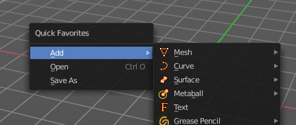
Order
You might notice that the add menu adds at the top of the menu, and not at the bottom as you would expect. First comes menus, then comes operators. And they get added in the order in which you add them.
Besides that, operators and menus gets added in the order that you add them. They cannot be sorted afterwards. So be careful how you add them. You can of course always remove operators and menus, and re-add them at the end of the list.
Removing an operator from the Quick menu
The Quick Favorites menu (Q) holds the tools and menus you add to it yourself. See Quick Favorites in the Interface chapter.
Context and mode dependent content
The quick favorites. menu exists in nearly all editors. But it is just in the 3D view available in the header. So that you know this functionality exists. In the other editors you call it with hotkey Q.
The content of the quick favorites. menu changes, dependent over which editor you are, and in what mode you are. When you add for example an operator from the image editor, then this operator just shows in the quick menu when you call the menu from the image editor. Same goes for the modes. Edit mode tools will just show in edit mode. And so on.
View Menu
View Menu
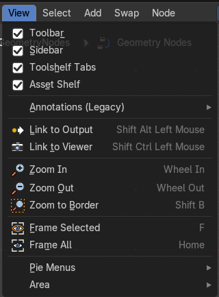
The View menu contains all View related tools.
The content is the same in all sub modes.
Toolbar
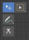
Shows or hides the toolbar at the left.
Sidebar
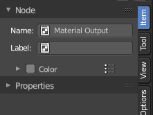
Shows or hides the sidebar at the right in the Geometry Nodes editor.
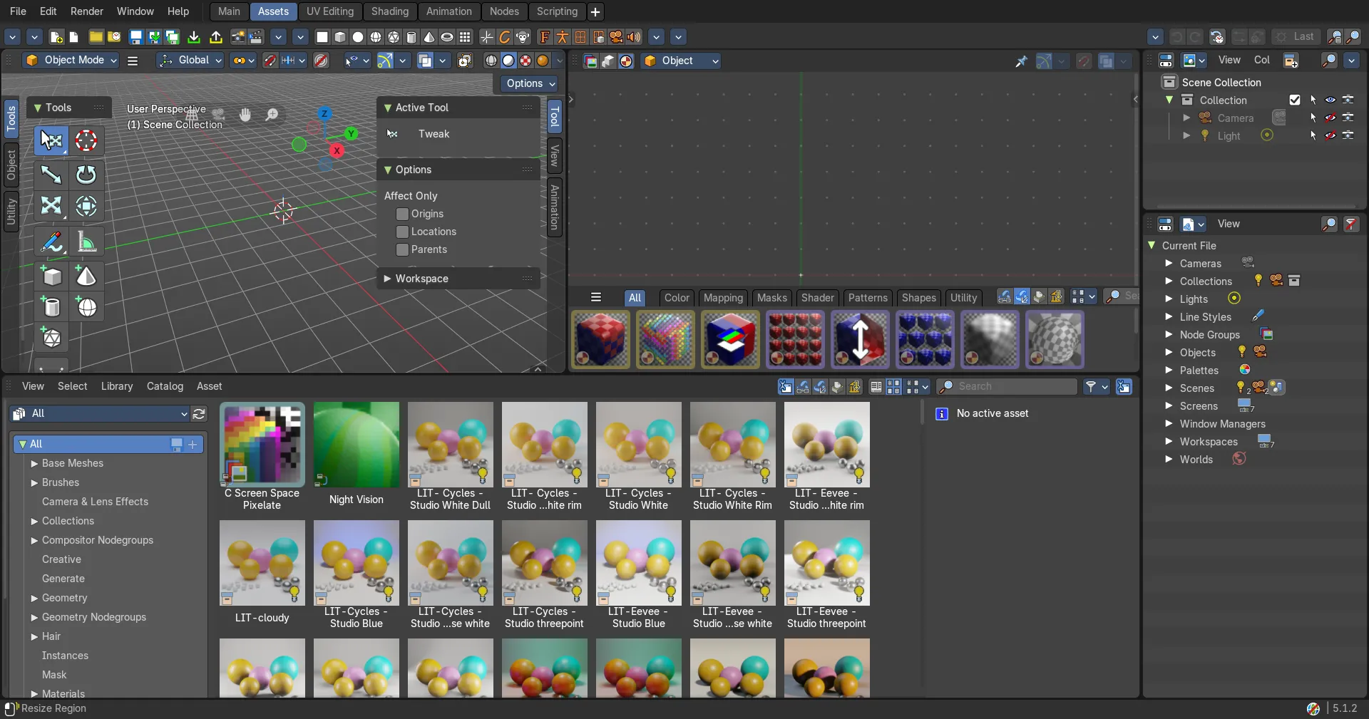
Asset Shelf
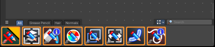
Shows or hides the Asset Shelf to the bottom of the Geometry Nodes Editor.
Annotations (Legacy)
This group of operators is useful to take notes without changing tool-shelf operators. These notes can be colored in the View tab of the Property Shelf. Each layer is a single color. You can also animate the notes with keyframes, editable in the dopesheet.
Note: These are legacy operators, meaning they are equally available in the Toolshelf as a modal operator.
| Entry | What it does |
|---|---|
| Draw Annotation | Starts the annotation free hand draw tool in the editor. |
| Draw Line Annotation | Starts the annotation line draw tool to draw straight lines in the editor. |
| Draw Polyline Annotation | Starts the annotation Polyline draw tool in the editor which allows to draw multiple connected straight lines in the editor. |
| Erase Annotation | Starts the annotation erase tool in the editor which erases any strokes in the editor. |
| Add Annotation Layer | Starts a new annotation layer. |
| Erase Annotation Active Keyframe | Erases the active keyframe of the annotation. |
| Entry | What it does |
|---|---|
| Link to Output | Creates a connection to the Output Node. Note: This operator only works under the mouse cursor and is shown in this menu for discoverability purposes only. |
| Link to Viewer | Creates a temporary connection to the Viewer Node, allowing to quickly preview the output of any node within the shader editor by clicking on it. Note: This operator only works under the mouse cursor and is shown in this menu for discoverability purposes only. |
| Zoom In | Zooms into the viewport. |
| Zoom Out | Zooms out of the viewport. |
| Zoom Border | Draws a rectangle and zooms then to fit the size of this rectangle. Zooming in is done with drawing the rectangle with left mouse button. Zooming out is done with drawing the rectangle with middle mouse button. |
| Frame Selected | Zooms to the selection. |
| Frame All | View all zooms in or out in the viewport until all objects in the scene are displayed fitting in the viewport. |
Pie menus

Lists the available pie menus, and gives you the ability to read the hotkeys and assign own hotkeys.
Area
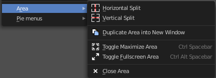
This menu contains general view functionality. And exists in most other editor types too.
| Entry | What it does |
|---|---|
| Horizontal Split | Splits the current view horizontally into two independent editor windows. |
| Vertical Split | Splits the current view vertically into two independent editor windows. |
Duplicate Area into New Window
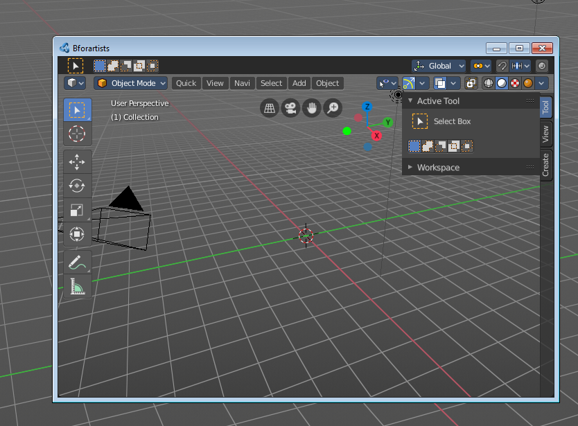
Duplicate Area into New Window opens this editor in a floating window. See Floating editor windows in the Interface chapter.
| Entry | What it does |
|---|---|
| Toggle Maximize Area | Displays the editor maximized with menus. To return from the maximized view press hotkey Ctrl + Space. Or reuse the menu item in the area menu. |
| Toggle Full screen Area | Displays the editor maximized without menus. To return from the full screen view press hotkey Ctrl + Alt + Space. |
| Close Area | Closes the area window. |
Select Menu
Select menu
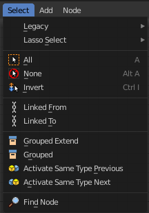
Here you will find the select functionality.
Legacy

The legacy sub menu contains tools that exists in the tool shelf already. It's the old way to do things. Different to the tools in the tool shelf, these tools are usually modal. And performs once. You have to call them again in case you want to repeat the tool.
| Entry | What it does |
|---|---|
| Box select | Draw a rectangle to select everything inside of the rectangle. It automatically adds to the current selection. Holding down shift subtracts from the selection. |
| Circle select | Brush select content. The radius of the brush can be adjusted by holding down left mouse button and using the scroll wheel or the + or - button at the numpad. It automatically adds to the current selection. Holding down shift subtracts from the selection. To exit the circle select tool click with the right mouse button. |
Lasso Select

A sub menu with the available lasso select modes.
| Entry | What it does |
|---|---|
| All | Select everything. |
| None | Select nothing. |
| Inverse | Invert the current selection. |
| Linked From | Select the nodes that are linked from the currently selected nodes. The nodes before in the hierarchy. |
| Linked To | Select the nodes that are linked to the currently selected nodes. The nodes behind in the hierarchy. |
| Grouped | Select grouped nodes. |
| Grouped Extend | Select grouped nodes, and extend from the current selection. |
| Activate same type previous | Activate same node type before the current selection, step by step. |
| Activate same type next | Activate same node type after the current selection, step by step. |
Find Node
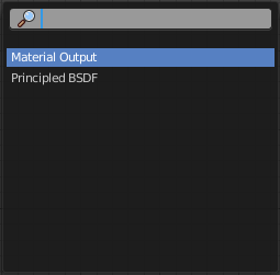
This button will open a search dialog where you can search for node types and select them in the current hierarchy.
Swap Menu
Swap
Replace the selected node by another node from the swap menu.
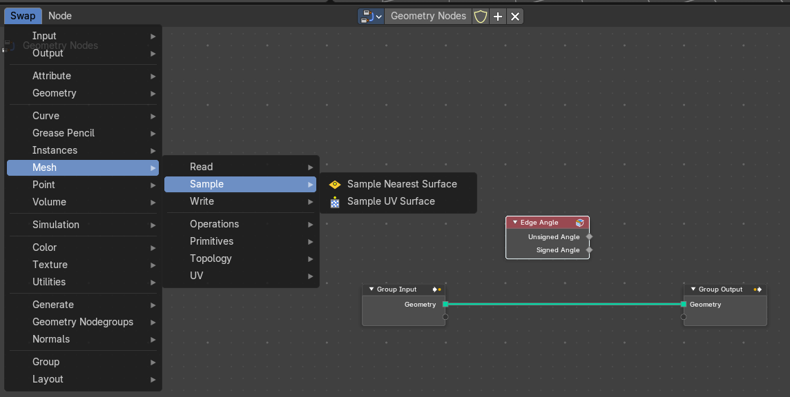
Node Menu
Node menu
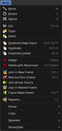
This menu contains further node functionality.
Move
Moves the selected nodes.
Rotate
You can't rotate single nodes, obviously. But when you have more than one selected then you can rotate them around their center point.
Resize
You can't resize single nodes, obviously. But when you have more than one selected then you can scale them around their center point.
Cut
Copies the selected nodes to the clipboard and removes them, keeping the links around them connected. Paste them back with Paste. Hotkey Ctrl + X, like in most programs.
Copy
Copies the selected node(s) to the clipboard, for reuse with the paste operator in the current or other instances of Bforartists that are open.
Paste
Pastes the selected node(s) from the above mention copy operator that are in the clipboard, in the current session of Bforartists or another instance that are open.
Duplicate Keep Input
This works at nodes that have a connected input. Duplicating will keep the input connections established in the duplicated node. The output connections will be removed.
Duplicate
Duplicates the selected node(s). All connections will be removed in the duplicated node.
Delete
Deletes the selected node(s).
Delete with Reconnect
Deletes the selected node(s). When this node is in the middle of a connection, then the connections will be reconnected.
Join new Frame
Frame node functionality. Adds the selected node to a frame.
Remove from Frame
Frame node functionality. Removes the selected node from a frame.
Join Group Inputs
Merge selected group input nodes in one if possible.
Join in Named Frame
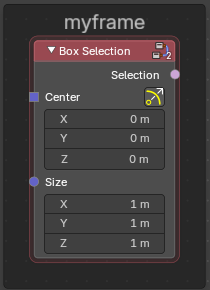
Create a new frame node around the selected nodes and name it immediately.
To remove the node from the frame , right click and choose Remove from Frame.
Frame Make Parent
Frame node functionality. Adds the selected node to a frame.
Rename
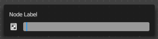
Allows you to rename the selected node. A popup dialog will appear where you can change the name of the node. Press enter to make it real.
Group
Make Group
Groups the selected nodes together.
Select the nodes that you want to group together. Choose Make Group. You will now see a green background. This indicates that the group is created, and that you are in edit mode for the group now.
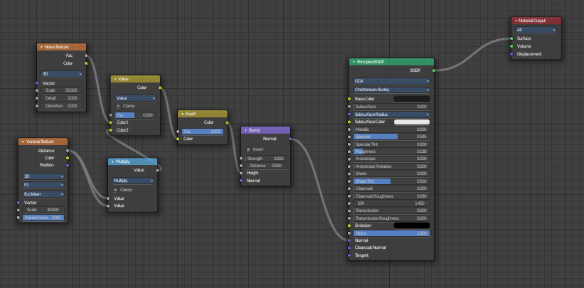
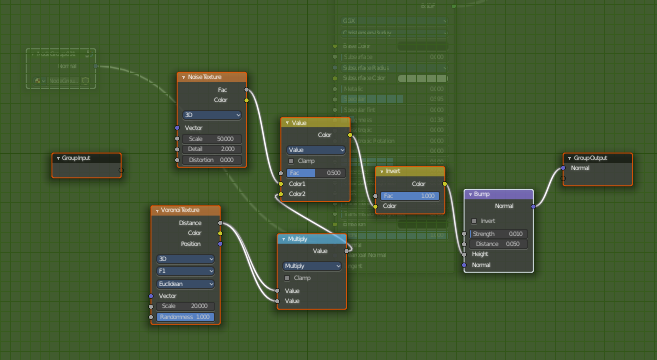
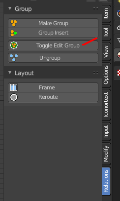
To exit the group edit mode press Tab key, or choose Toggle Edit Group menu item in the sidebar in the Relations tab in the Group panel. That way you can also enter the Group Edit mode again.
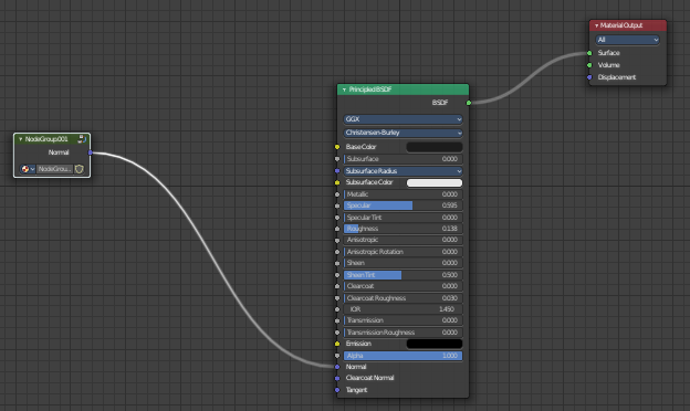
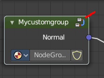
There is a third way to enter the group edit mode. Click at the right upper icon of the group node.
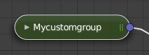
A group can be further collapsed by clicking at the triangle button in the upper left corner.
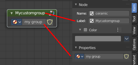
The group can be renamed in the sidebar in the Item tab and in the Properties tab in the Node panel.
| Entry | What it does |
|---|---|
| Insert into Group | Allows you to insert a node into a node group. Select the node, hold down Shift, then select the node group so that both are selected. Then perform the operator. |
| Ungroup | Ungroups an existing group. You need to be outside of the group edit mode. |
| Toggle Edit Group | Enters a node group for editing. Or when you are in a node group, exits the node group editing. |
Links
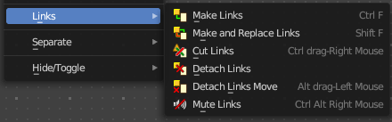
| Entry | What it does |
|---|---|
| Make Links | Tries to connect nodes where it makes sense. |
| Make and Replace Links | Same as Make Links. But it will replace existing links. |
| Cut Links | Mouse only tool. Cut links by moving with the mouse over the connection |
| Detach Links | Removes all connections from the selected node, but tries to reconnect the remaining nodes. |
| Detach Links Move | Removes all connections from the selected node by dragging. |
Mute Links
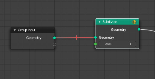
Allows you to mute links instead of disconnecting it by painting over the link connection. To unmute, use the tool again. Hotkey only tool. Please use the hotkey.
Separate

Node group functionality. You need to be in edit group mode.
| Entry | What it does |
|---|---|
| Copy | Copies the selected node, and pastes a copy of it outside of the node group. The node group remains unchanged. |
| Move | Moves the selected to outside of the node group, and removes it from the node group. |
Hide / Toggle
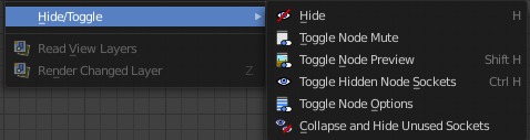
Here you find hide options to make the display of nodes
more compact.
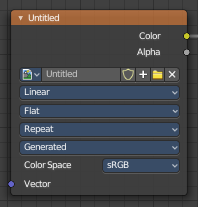
Demonstration happens at an image node.
Hide
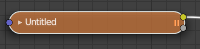
Hides everything but input and output dots. To view the full node again perform the operator again. It's a toggle. Or click at the triangle left besides the node name.
Toggle Node Mute
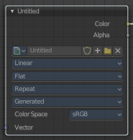
Deactivates the node.
Toggle Node Preview
This is a compositor feature for the preview image. It does not belong here, but shares the same menu. It shows or hides the preview image.
Toggle hidden node sockets
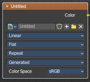
Toggles away the unused node sockets. In this case the vector input node socket and the alpha output node socket will be hidden.
Toggle Node Options
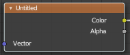
Hides away the properties.
Collapse and Hide Unused Sockets
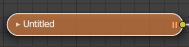
Like Hide. Hides everything but the node sockets. But it also hides the unused node sockets.